When I was very young. I had the vision I wanted to be a pilot.

It originally started with me wanting to join the Royal Navy to be a fast jet and helicopter pilot. However a few factor caused this dream to fall apart. For one, I was too tall and was told “It’s cheaper to find shorter people than to make bigger planes”.

Fast forward many years and eventually I achieved my goal of becoming a pilot.

The next adventure for me was to own an aircraft. While it wouldn’t make the cost of flying that much cheaper. It would give me the (emotional and physical) freedom to go on adventures anywhere and when I wanted to.

One of the biggest criterial I had was that the airplane needed to fit larger sports equipment. Think bikes and snowboard bags – these aren’t small items.

Big Luggage

I decided to go down the route of building a plane. 1) I wasn’t prepared to drop +1 Million USD for an aircraft 2) The lead time for anything is +24 months.

In the end I decided to build a Velocity Aircraft, its a pusher style aircraft with the engine in the back and a swept back wing design that doesn’t need flaps.

Velocity Aircraft


As part of my project, I opted to have the factory build my wings and fuselage as part of a program called ‘fast build’. This takes the pressure off me to build such vital components.

I also opted to take advantage of their ‘builder assist program’, where I spent two weeks at the factory learning some of processes such as fiber glass work and shaping/molding using composite materials.

Let me talk you though some of the areas I chose to focus on while at the factory.

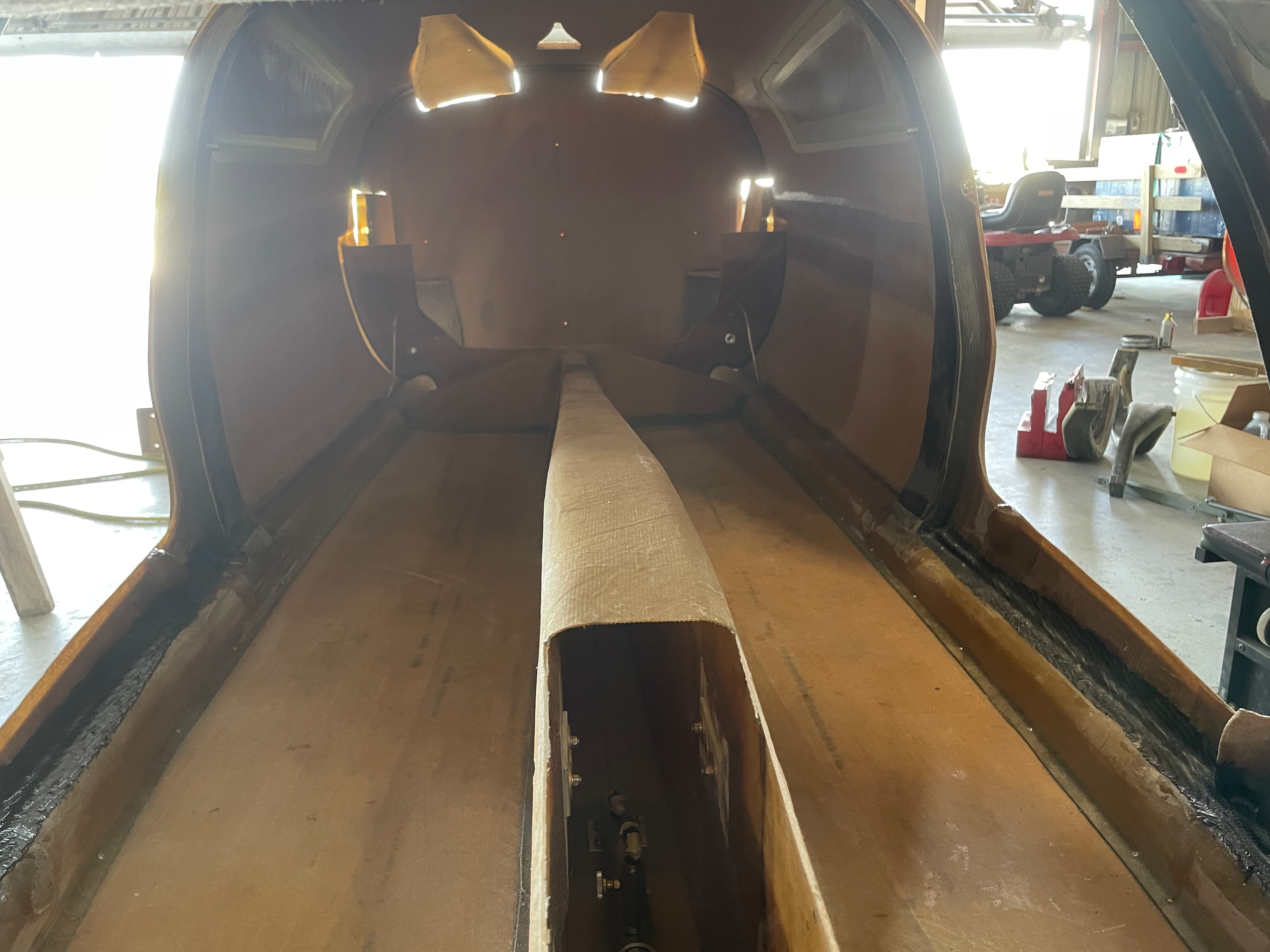
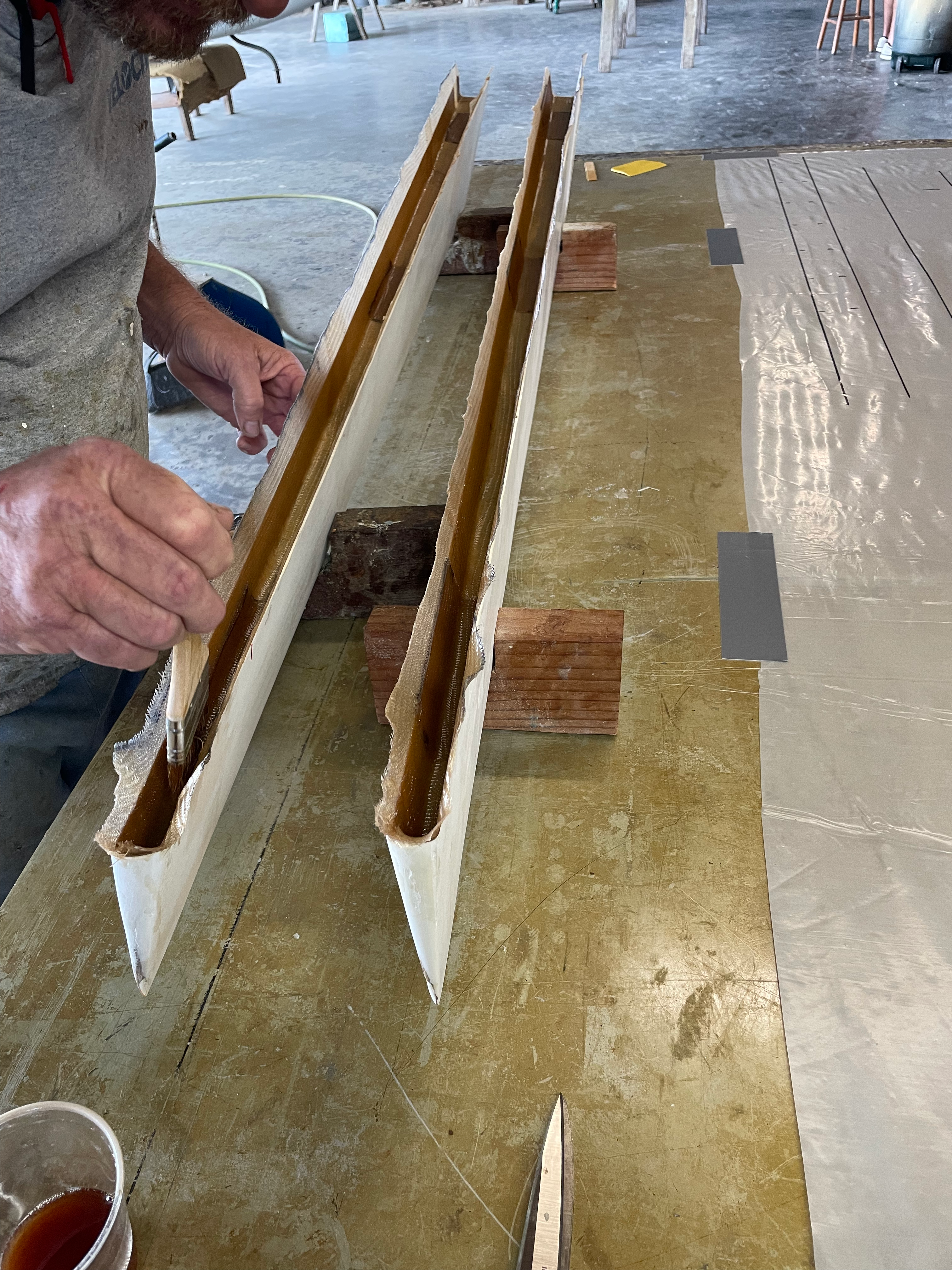
  • Here is the fuselage preassembled as part of the fast build.
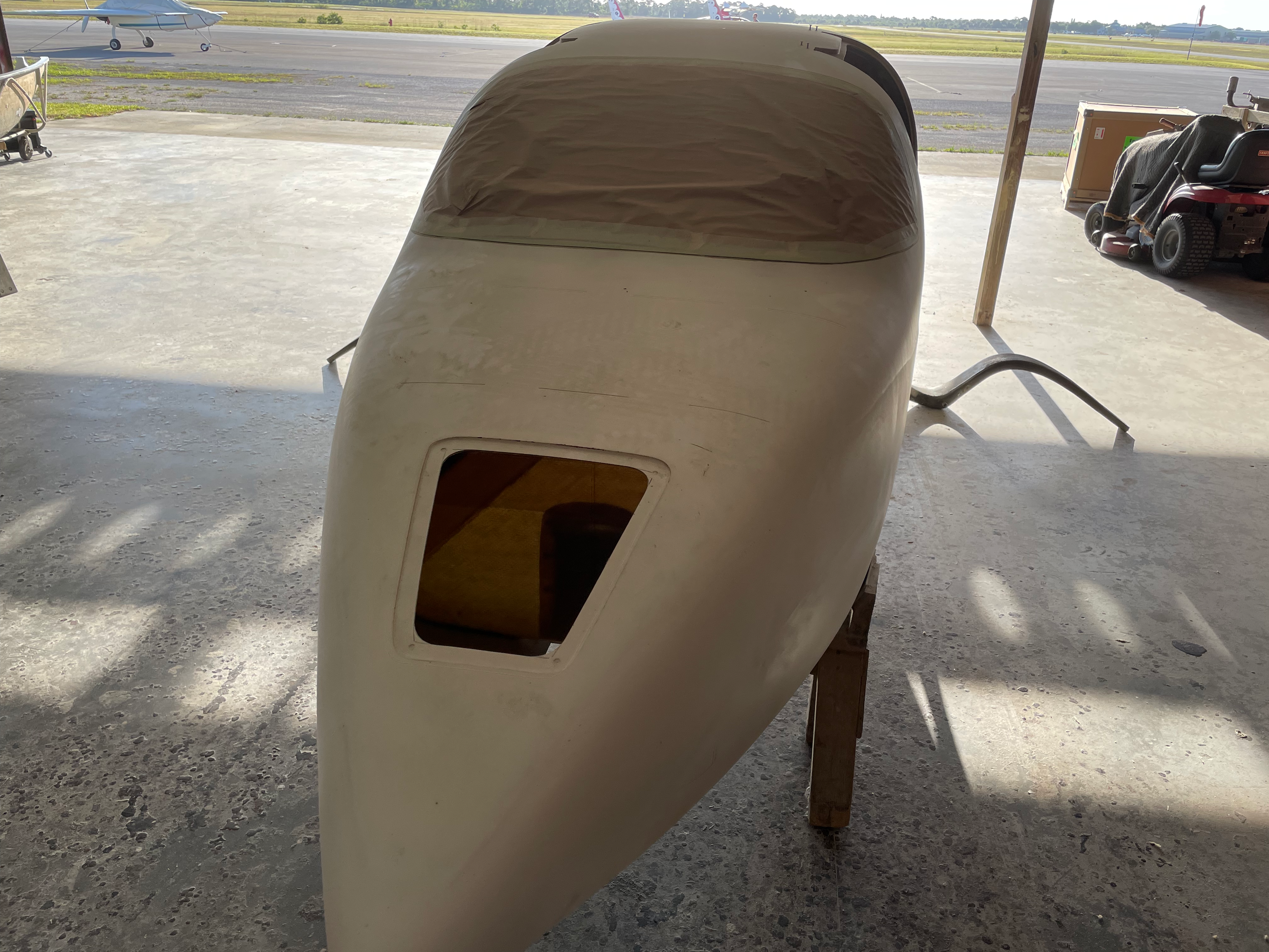
    Airplane Fuselage

    Airplane Fuselage

  • Here is the keel of the airplane removed so that additional material can be added to stiffen and reenforce the landing gear.
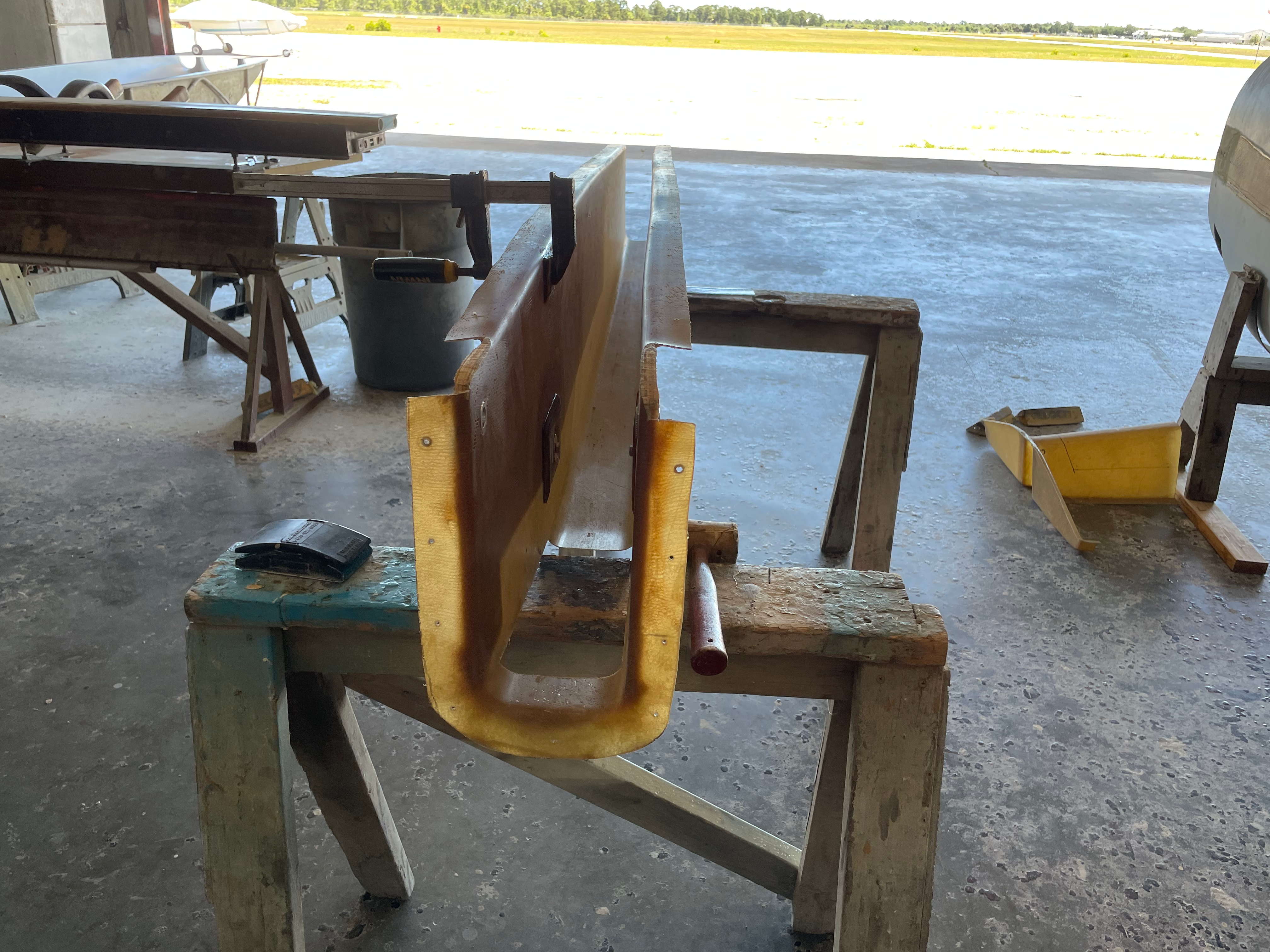
    Airplane Keel

    Airplane Keel

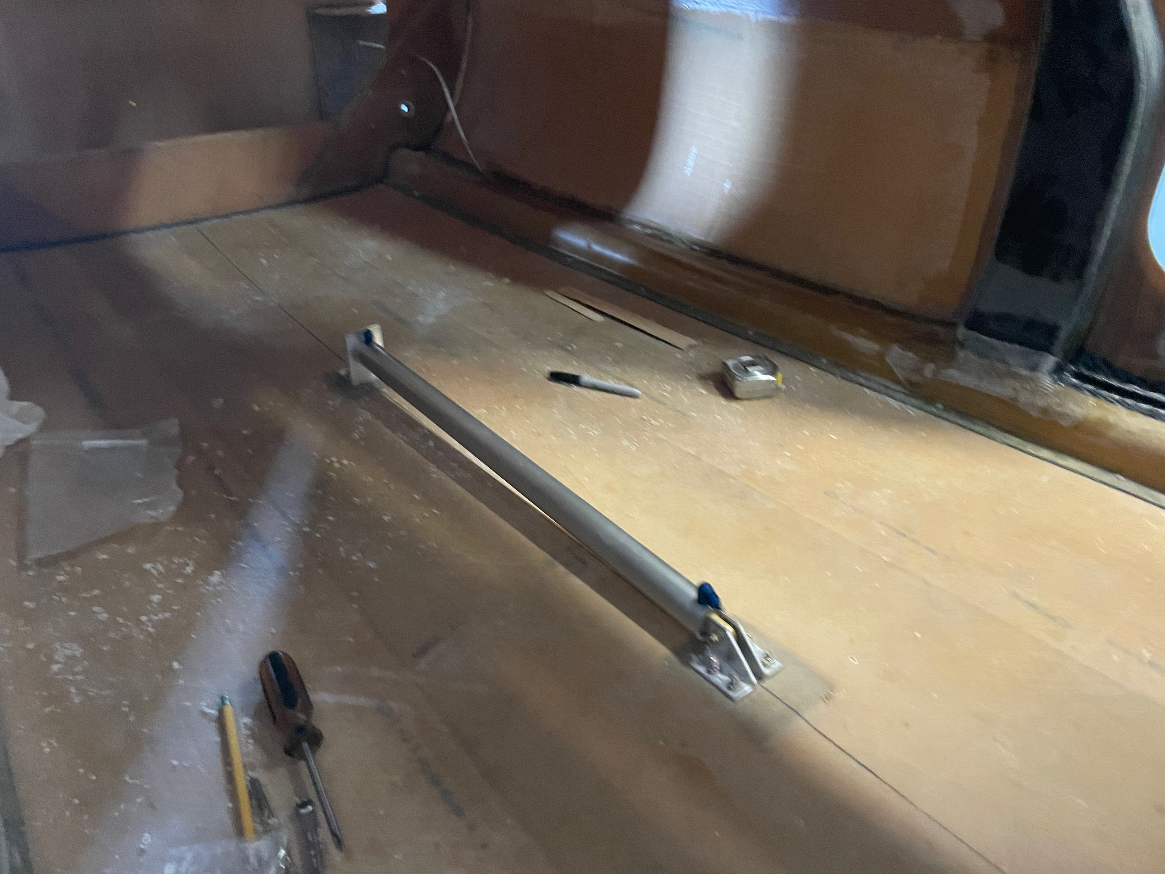
  • Rear legs for landing gear are removed to install brake lines.
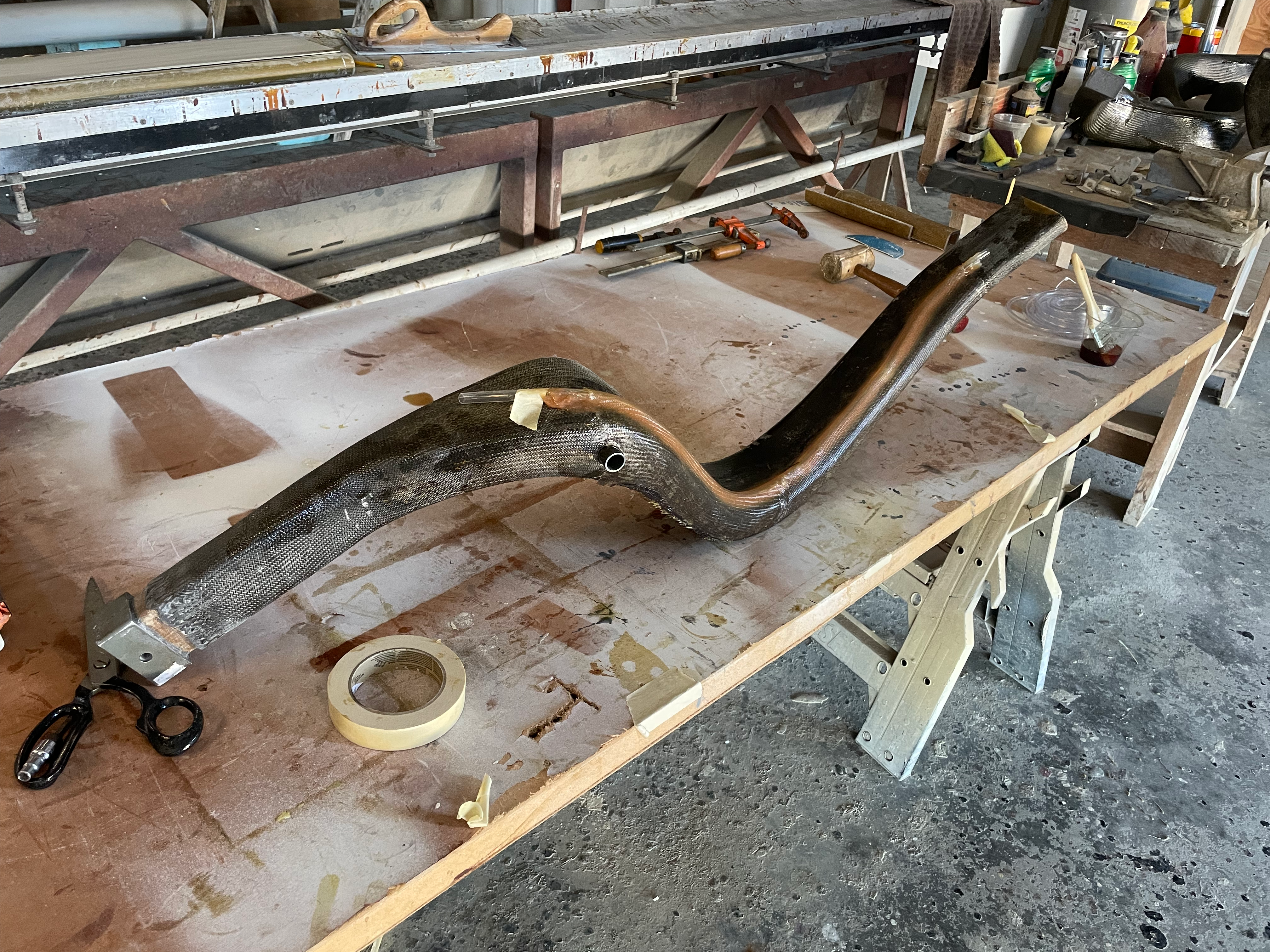
    Landing Leg

    Landing Leg

  • Here the elevators are being installed and aligned to fit the canard shape. The canard and elevators are currently upside down.
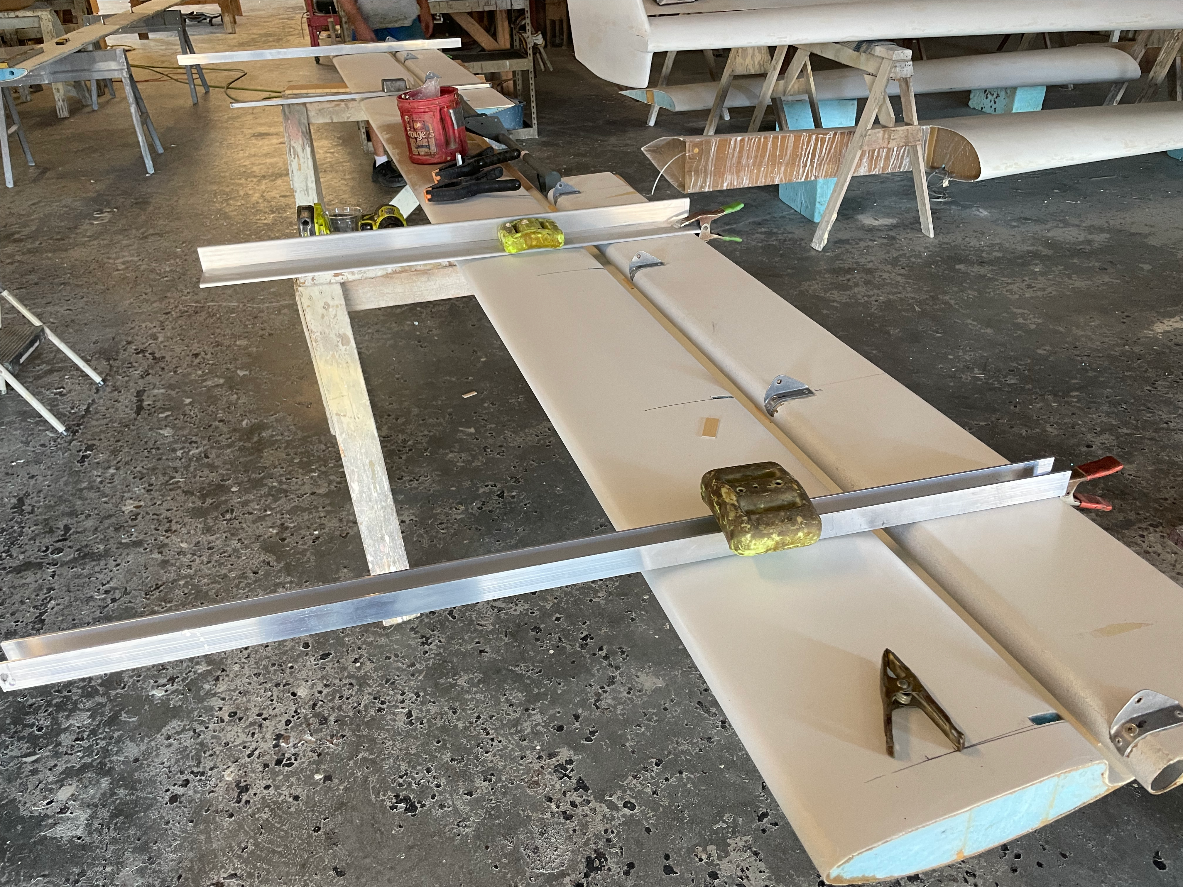
    Canard and Elevators

    Canard Elevators

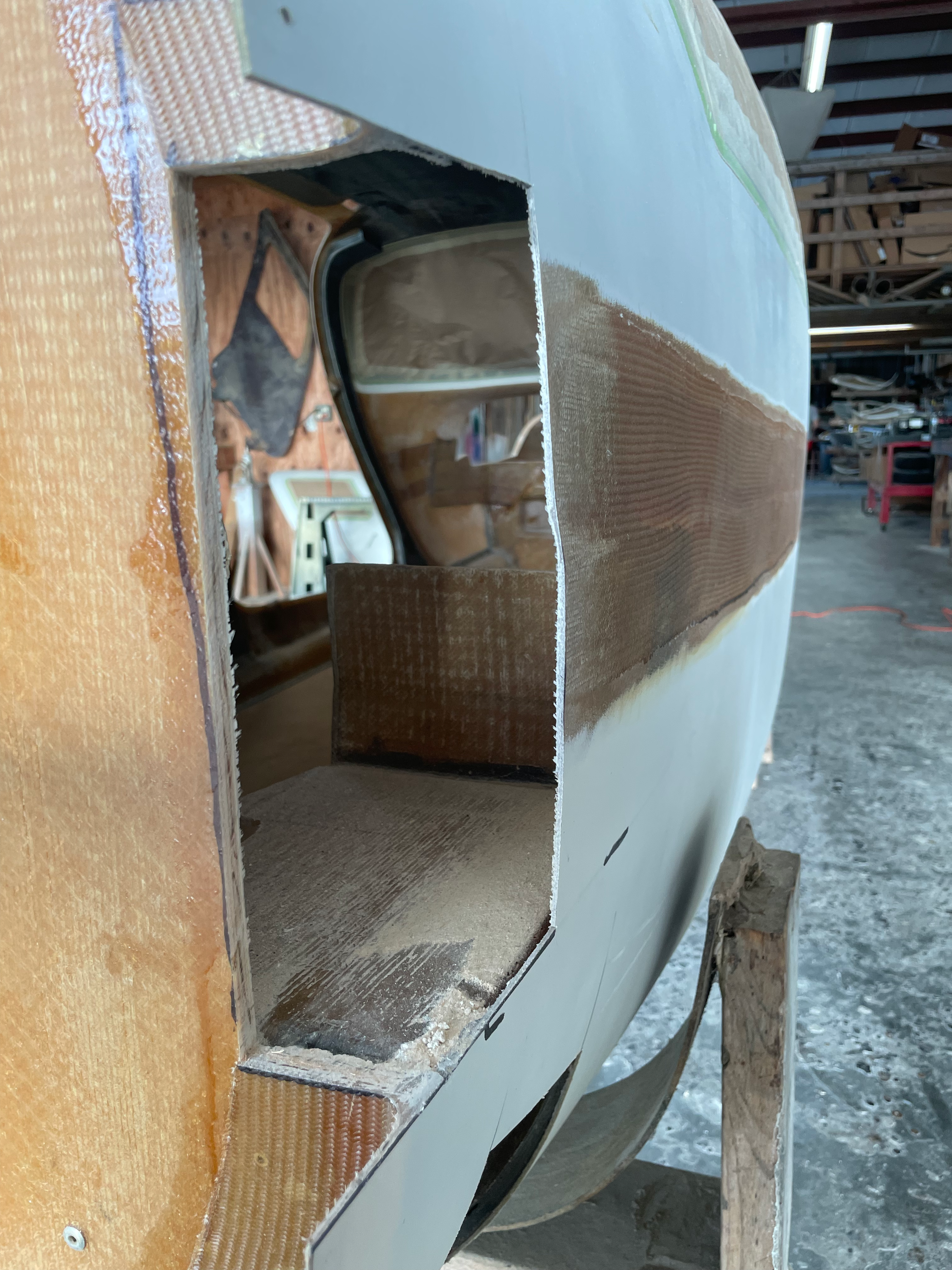
  • Rudder cut out for additional glassing and work.
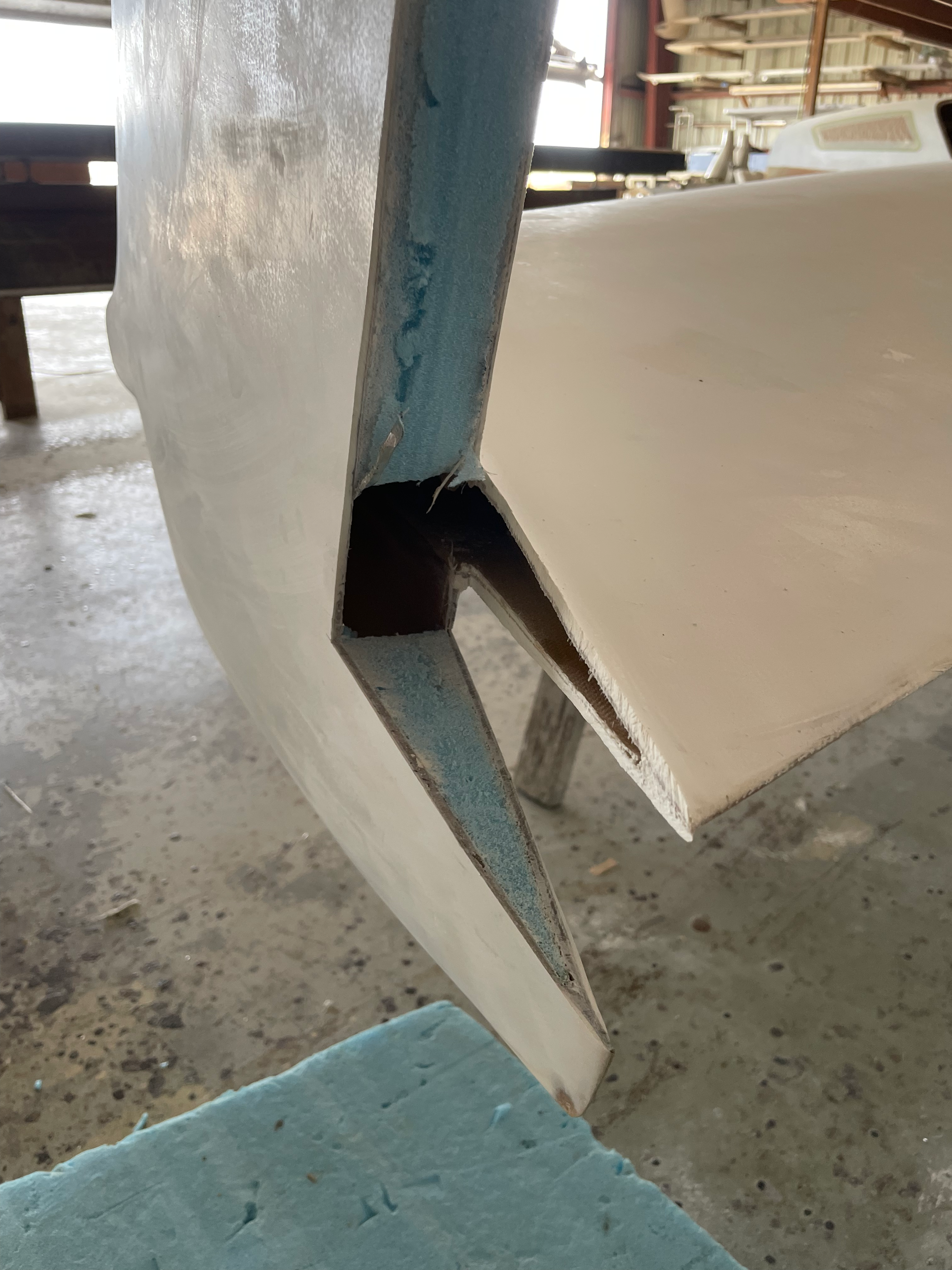
    Rudder Cutout

    Rudder Cutout

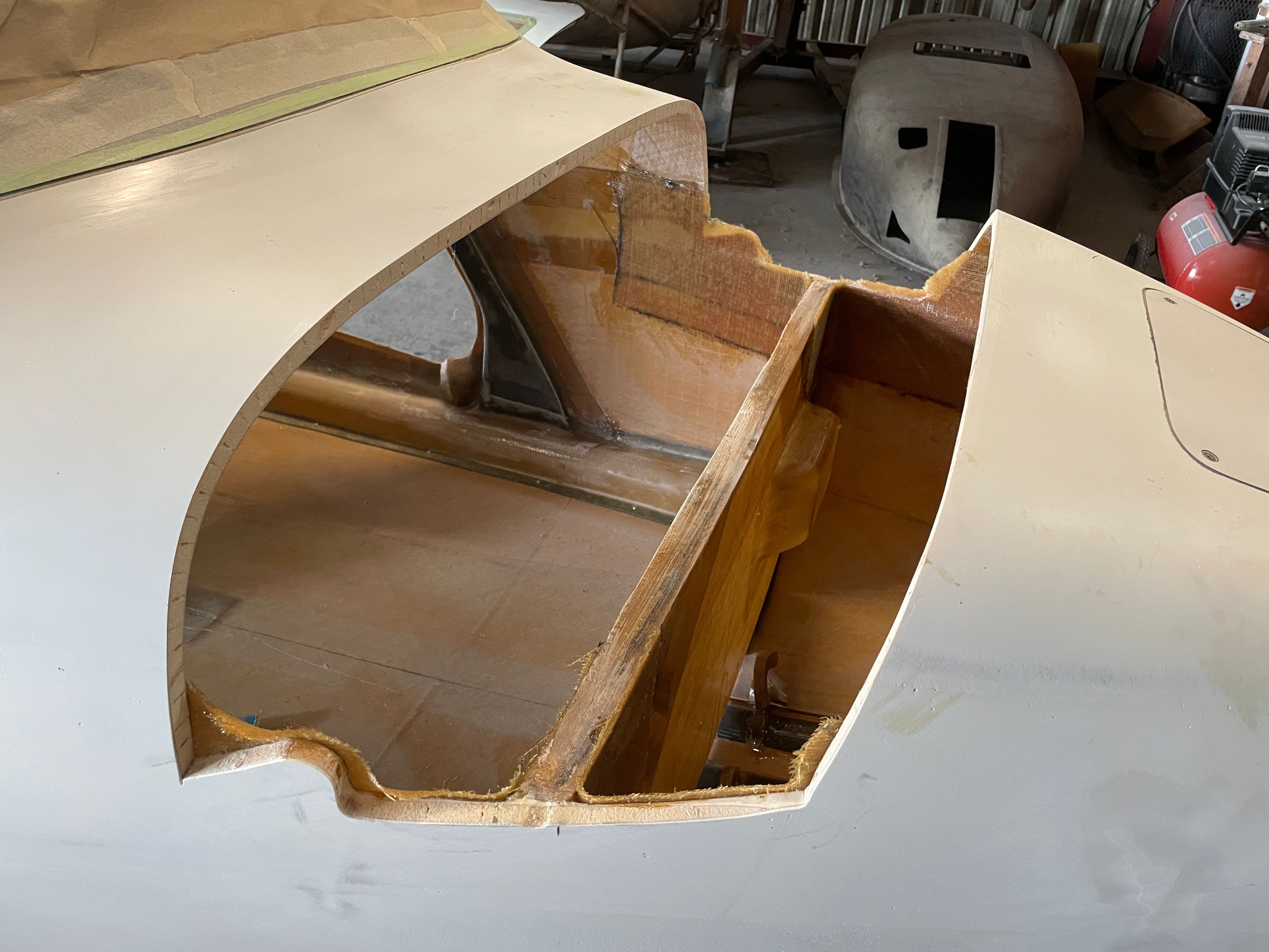
  • Canard / Doghouse Cut out.

    Canard Cutout

    Canard Cutout

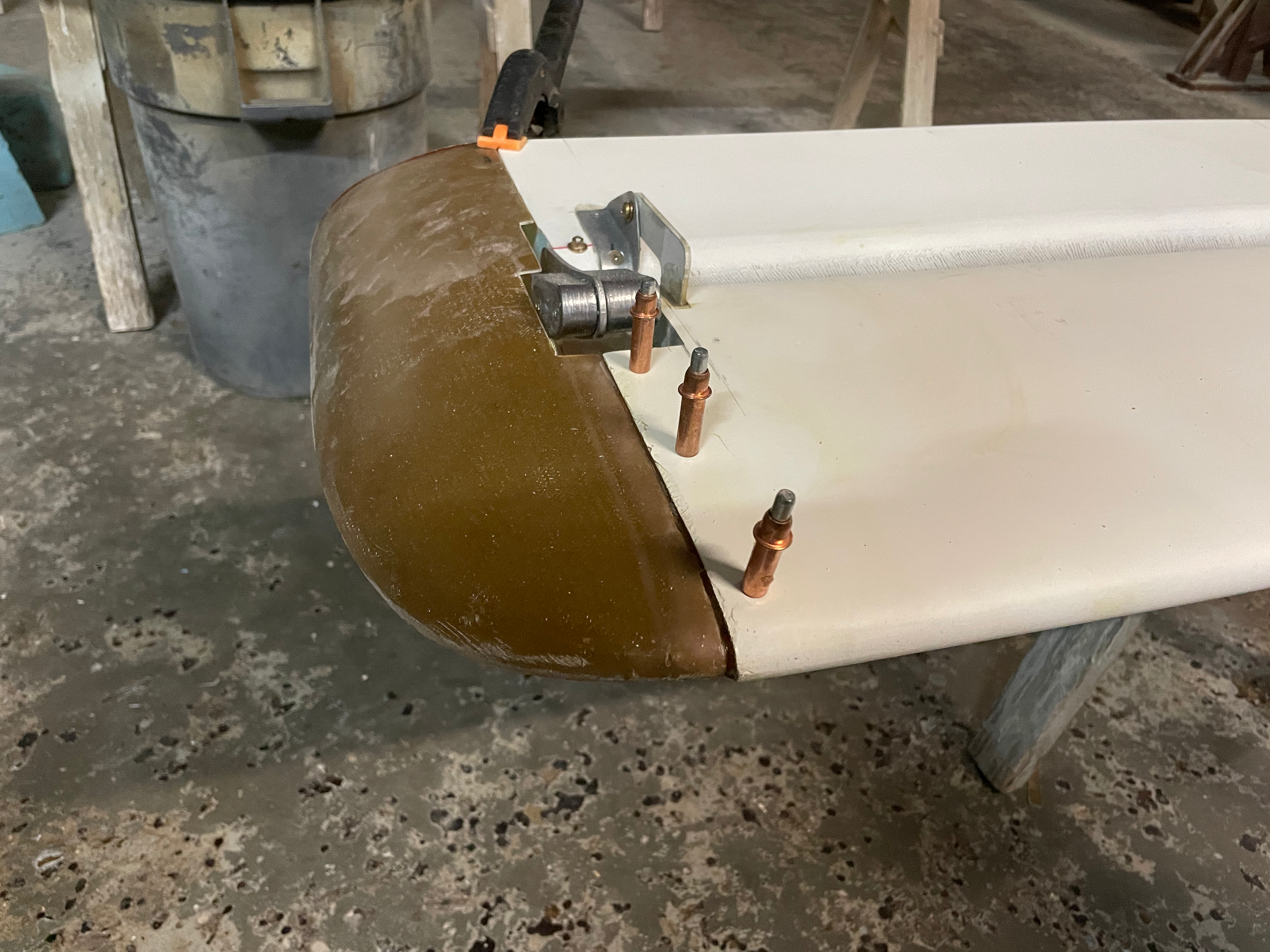
  • Wing Tips being added to Canard.

    WingTips

    Wing Tips

  • Rudder Conduit being glassed into place.
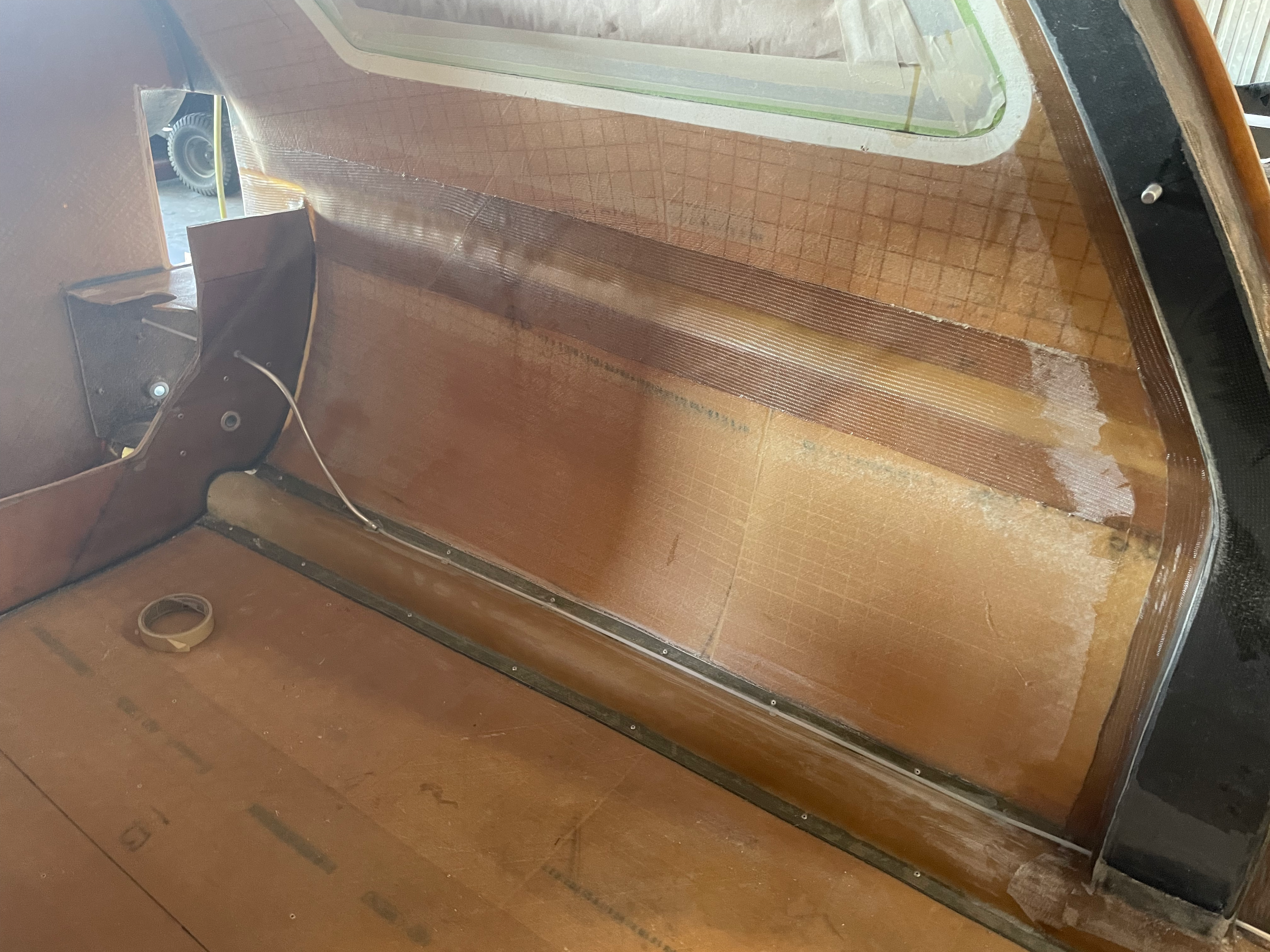
    Rudder Conduit

    Rudder Conduit

  • Landing gear hydraulic installed

    Landing gear hydraulic

    Landing gear hydraulic

  • Keel Permanently installed

    Keel Installed

    Keel Installed

  • NACA ducts installed and holes for spar cut out.
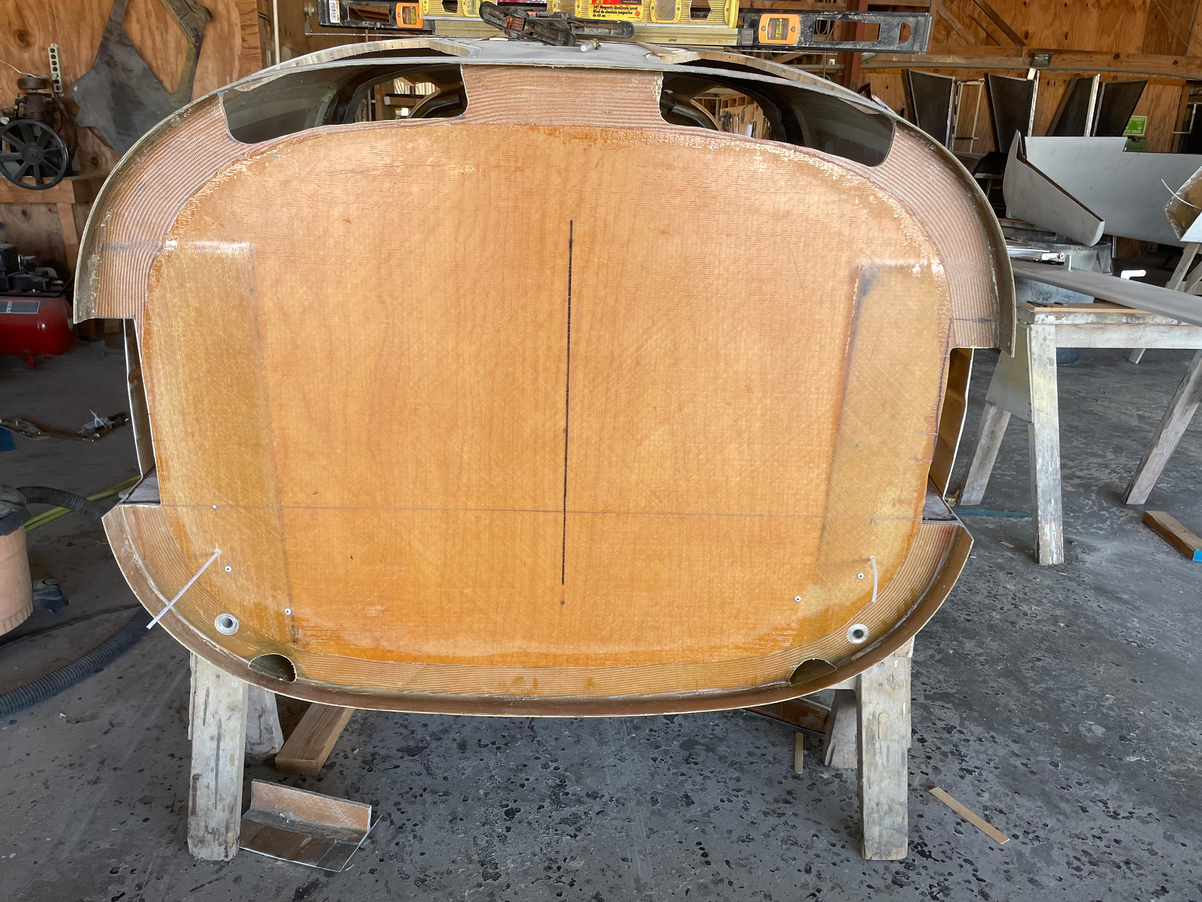
    Rear view

    Rear View

  • Wing tips skimmed and blended to canard.
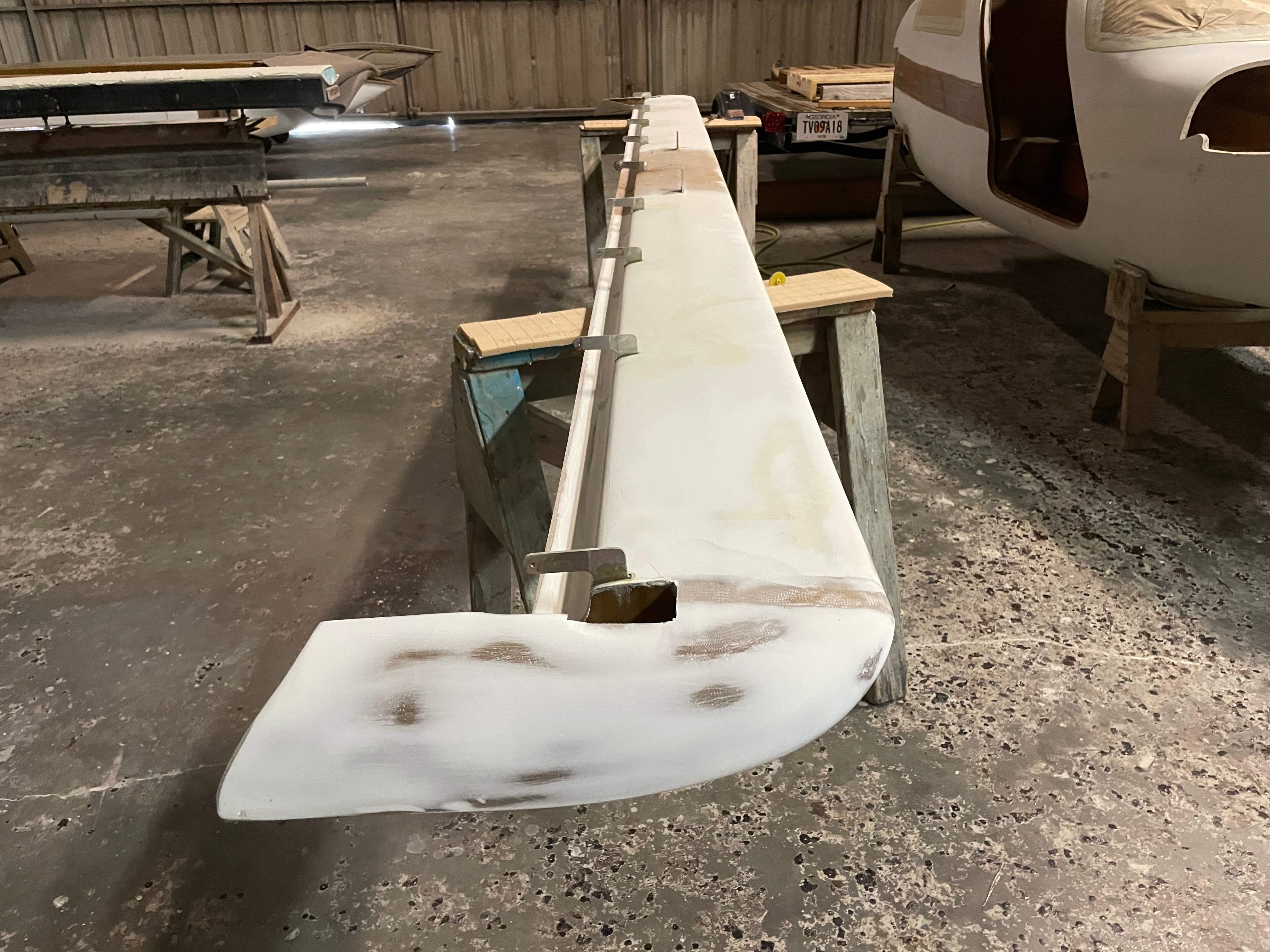
    Wing Tips Skimmed

    Wing Tips skimmed

  • Rudder internals being glassed.

    Rudder's being glassed.

    Rudder’s being glassed.

  • Center Spar holes being cut.

    Slots for center spar are cut

    Slots for center spar are cut

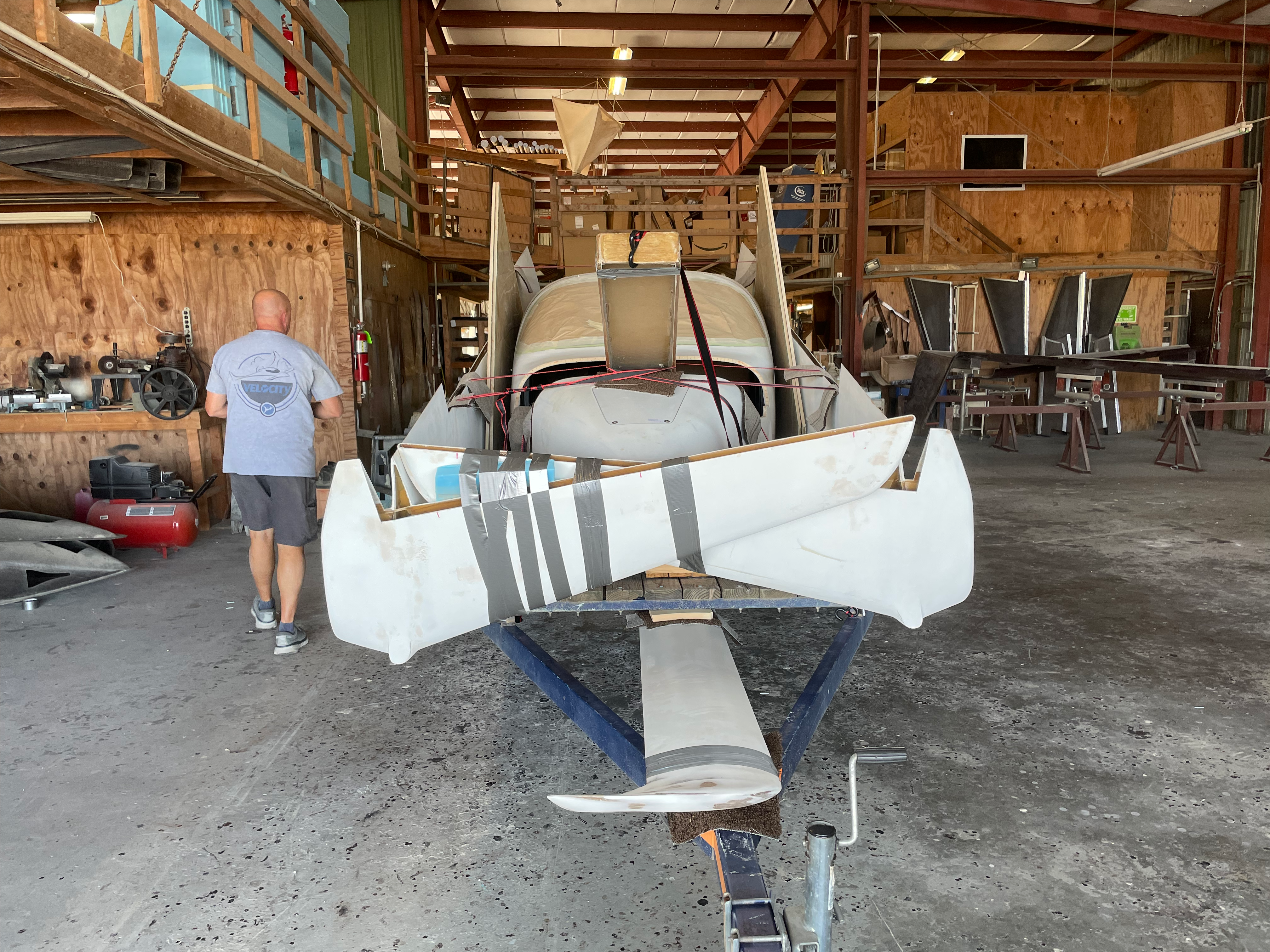
  • All packed up

    All loaded onto the trailer

    All loaded onto the trailer

The notes from the two weeks are lite as I chose to spend more time making and less time documenting.
The hope is that from here on in, notes should be more detailed as I will be in a position to work, photograph and document more.
During construction I’ve found that the use of 3d printing of parts, tools and components has accelerated the build time and also increased the quality of the end result. 

Let me take you through a few parts that I’ve built so far. 

Radio Antenna Core Holder

All of the comm, nav and radio antennas used the the project are all fed through 3 ferrite cores that helps reduce the noise on the line. In the assembly manual they recommend that you use heat shrink tubing to secure each core to the line. However this does nothing to secure the cores to the body of the aircraft. 

What if something jabs or pulls at the core by accident. 

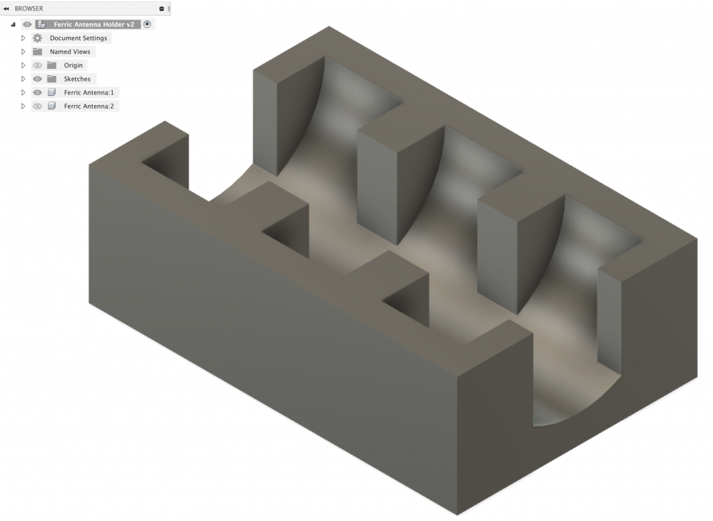
Enter printed component 1, a ferrite core holder that can be attached to wings, fuselages and any flat surface. It’s a two component design with identical top and base that clamshell together. 

Here’s the design in CAD:

Ferric Core Holder

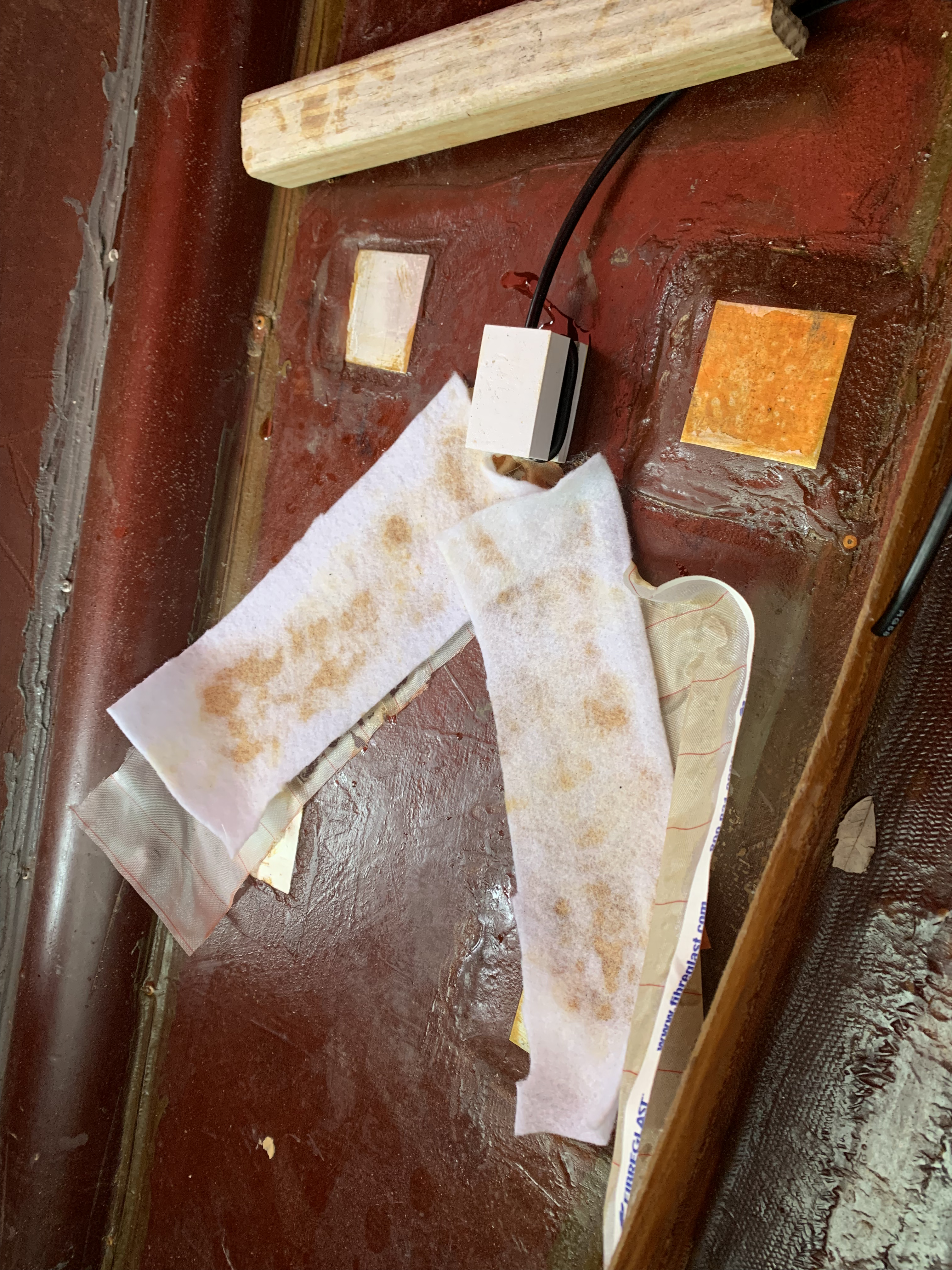
Here’s final assembly of the radio antenna and part.

3D part being installed

3D part being installed

Thoughts and conclusions;

The part was intentionally made to be a block rather than rounded surfaces. 

I wanted something that could be easily printed with a single component you could reuse without having to print a top and a bottom. 

There is enough material, that if you sand and round the top block once you have everything fixed in place. 

The flat surface allows you to fix the base to a bulkhead or fuselage and if you wanted to you could glass over the top with minimal work. 

You can find a copy of the file here.

Landing Gear Hydraulic Line Holders

Both the aluminum and flexible hose lines for the landing gear always look smarter when they are tidy and can’t move around. 

I was lucky enough to get a tour of a Gulfstream jet where they opened some of the panels and I was wow’ed at how neat all the lines and connectors were. 

Inspired by what I saw I wanted to replicate the same level of quality in my build. 

When it came to installing the hydraulic lines in the aircraft, I knew I wanted to keep everything sharp and neat looking so I measured the diameter of the hoses and printed up a top/bottom design that can hold the lines to prevent movement keep everything looking sharp. 

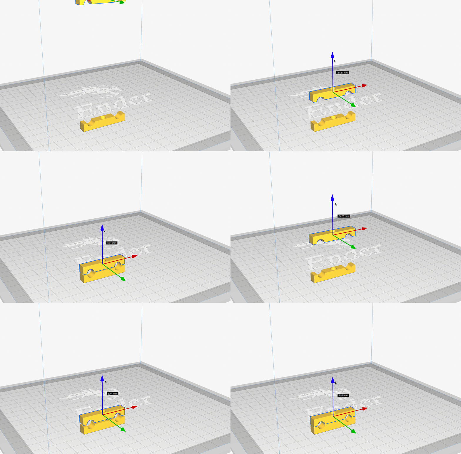
Here’s the design in CAD:

Screen Shot 2022-01-28 at 8.53.55.png

Here is a small clip of the top and bottom mating.

Example parts mating.

Here’s an example of how the parts look when mated.

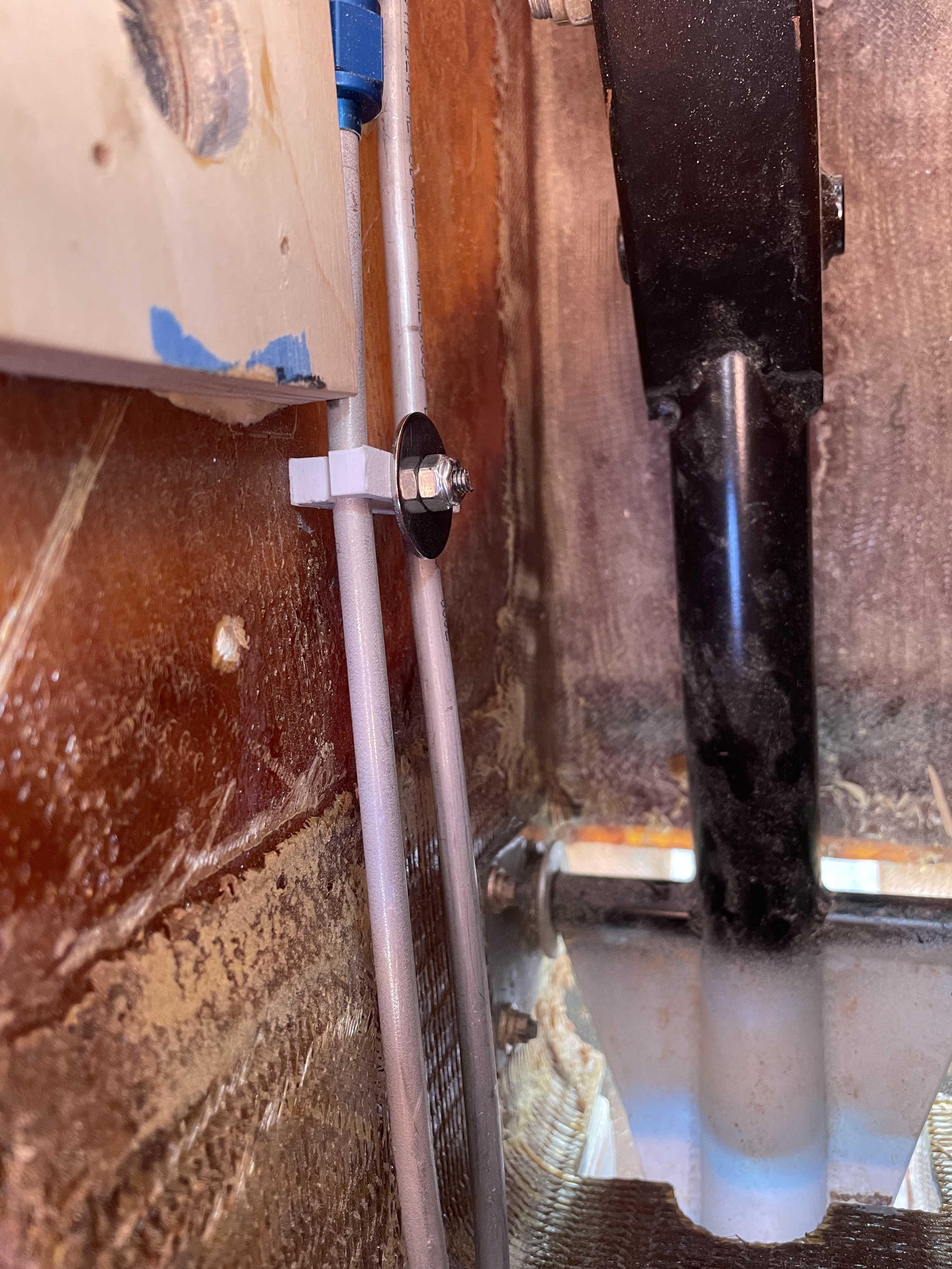
Here is the holder being used to secure the aluminum hydraulic lines in the forward bulkhead. 

3D Printed Hose Holder

3D Printed Hose Holder

As you can see, it’s a single component you can use for both top and bottom with a hole in the middle for a fastener. 

I’m big on multi use designs and hate having to design something that isn’t easy to use and easy to get going with. 

Not having to worry about if a part is the top or bottom of a component is a big timer saver. 

Thoughts and Conclusions 

The ability to keep the lines looking smart but also out of the way of other components means this was a double win. The hoses are secure and if anyone pops the lid to see what’s inside I hope they would be impressed with how neat everything is. 

As you can buy 3d filament in almost any color these days, its very easy to match the 3d printed parts to either the primary or secondary color of your aircraft so that all the parts match and that it looks like part of the build.

Overall I’m very enthused with the parts I’ve been able to make for the aircraft and I can’t wait to see what else I can design. 

I saw a few peoples projects using 3D printed parts for AC directional vents, which inspired me to see what else could be built with the printer.

If anyone has any parts they would like to see made or have any they want to show me I’d love to see what has been built!