When I was very young. I had the vision I wanted to be a pilot.
It originally started with me wanting to join the Royal Navy to be a fast jet and helicopter pilot. However a few factor caused this dream to fall apart. For one, I was too tall and was told “It’s cheaper to find shorter people than to make bigger planes”.
Fast forward many years and eventually I achieved my goal of becoming a pilot.
The next adventure for me was to own an aircraft. While it wouldn’t make the cost of flying that much cheaper. It would give me the (emotional and physical) freedom to go on adventures anywhere and when I wanted to.
One of the biggest criterial I had was that the airplane needed to fit larger sports equipment. Think bikes and snowboard bags – these aren’t small items.
I decided to go down the route of building a plane. 1) I wasn’t prepared to drop +1 Million USD for an aircraft 2) The lead time for anything is +24 months.
In the end I decided to build a Velocity Aircraft, its a pusher style aircraft with the engine in the back and a swept back wing design that doesn’t need flaps.

As part of my project, I opted to have the factory build my wings and fuselage as part of a program called ‘fast build’. This takes the pressure off me to build such vital components.
I also opted to take advantage of their ‘builder assist program’, where I spent two weeks at the factory learning some of processes such as fiber glass work and shaping/molding using composite materials.
Let me talk you though some of the areas I chose to focus on while at the factory.
- Here is the fuselage preassembled as part of the fast build.
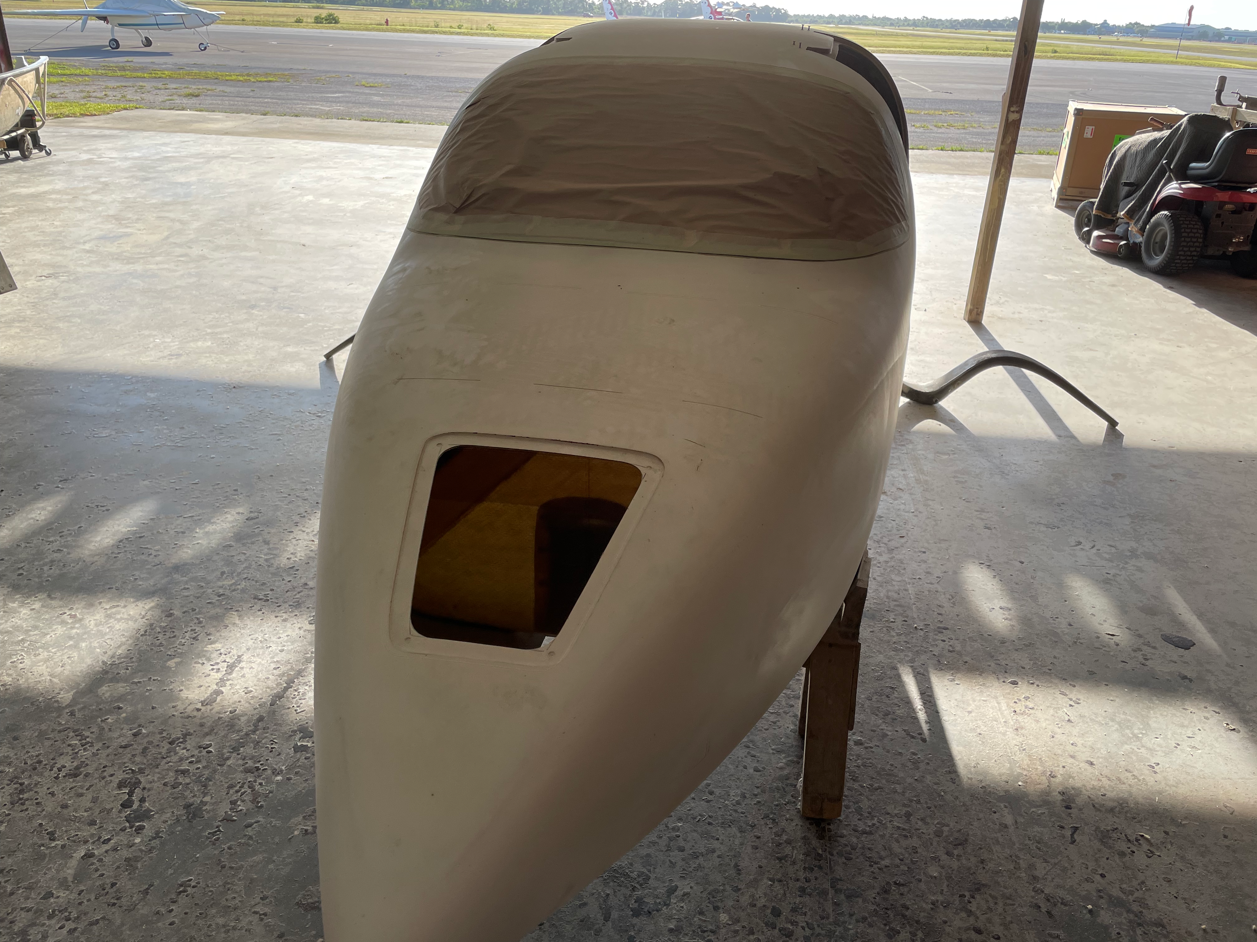
Airplane Fuselage
- Here is the keel of the airplane removed so that additional material can be added to stiffen and reenforce the landing gear.
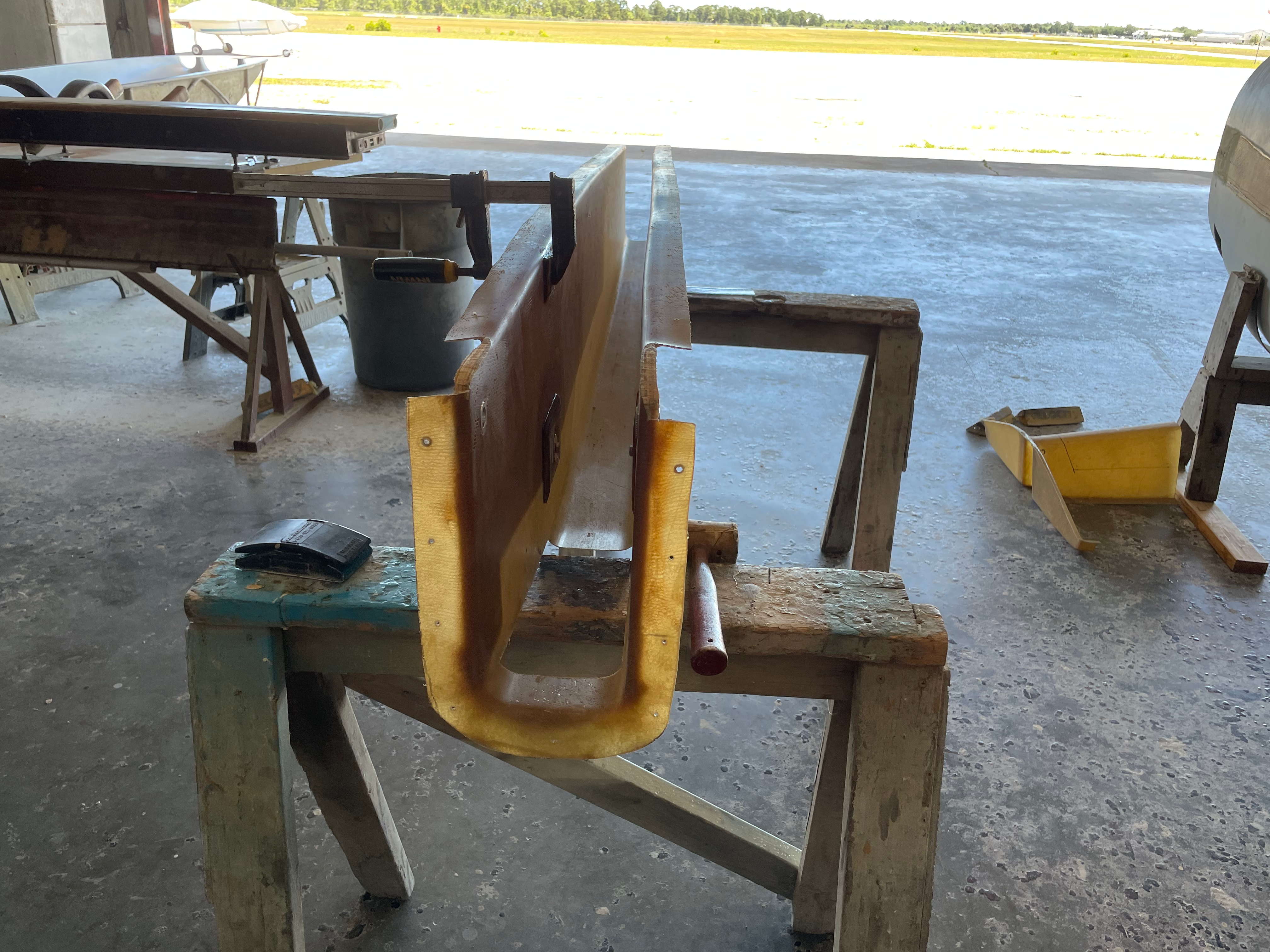
Airplane Keel
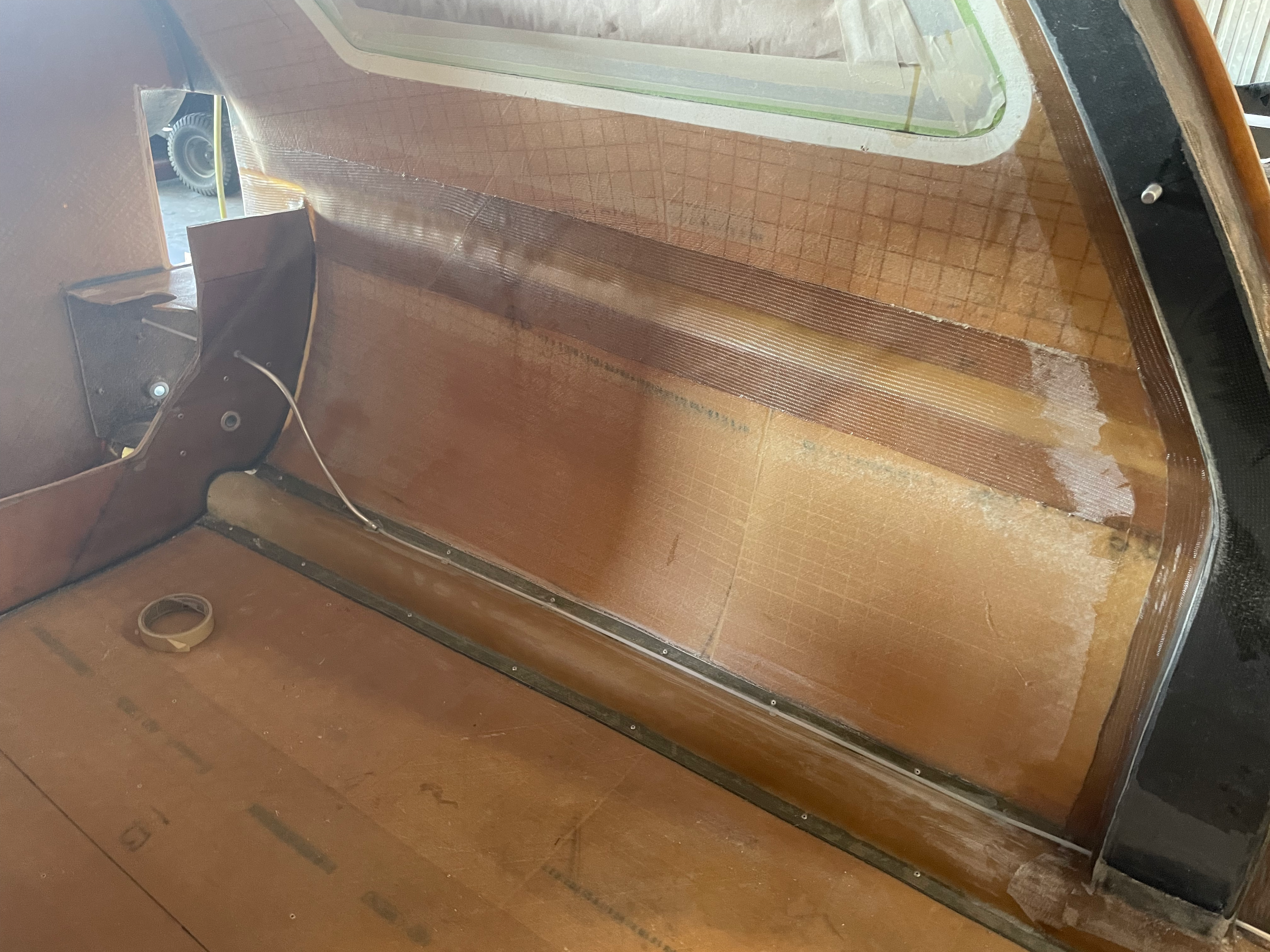
- Rear legs for landing gear are removed to install brake lines.
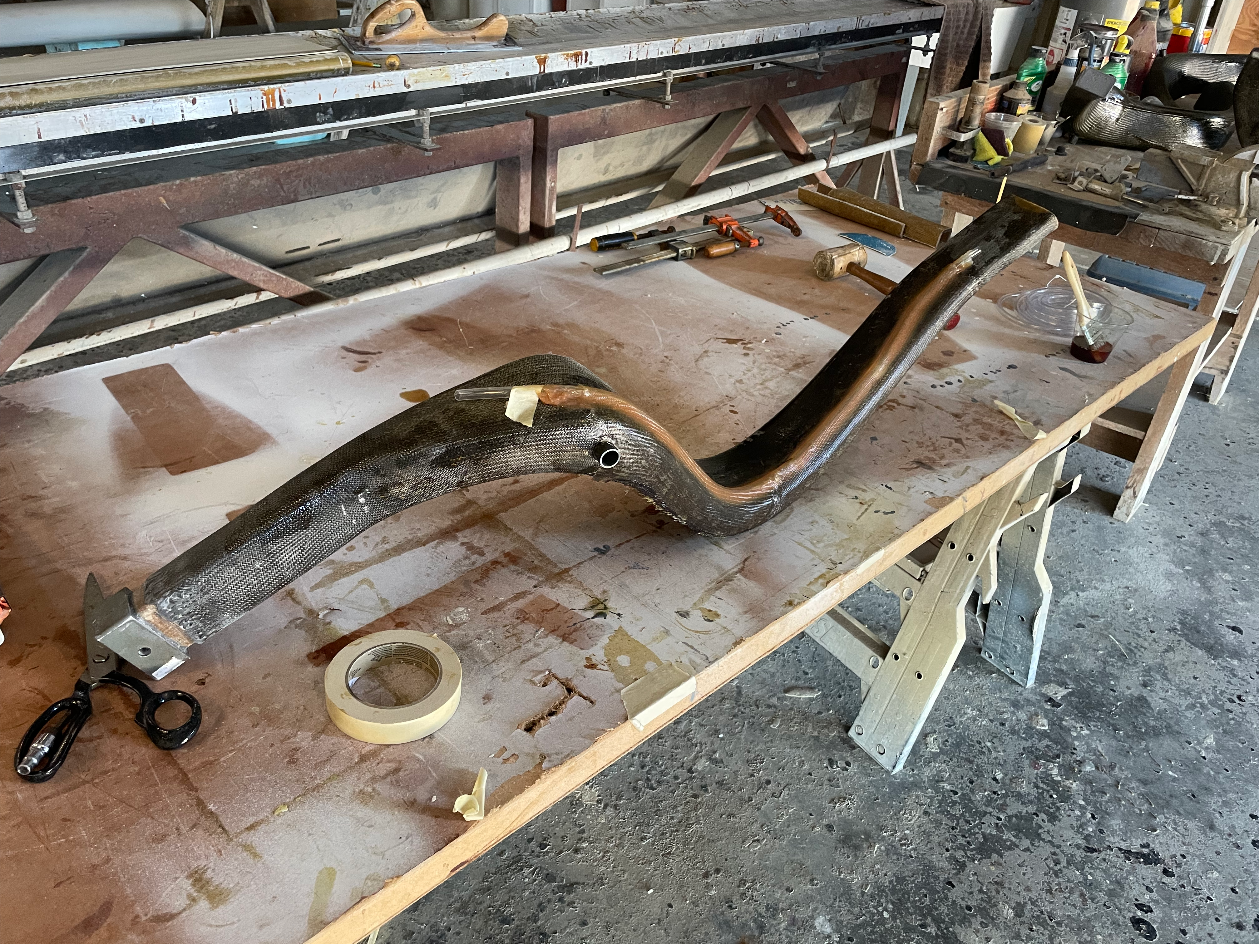
Landing Leg
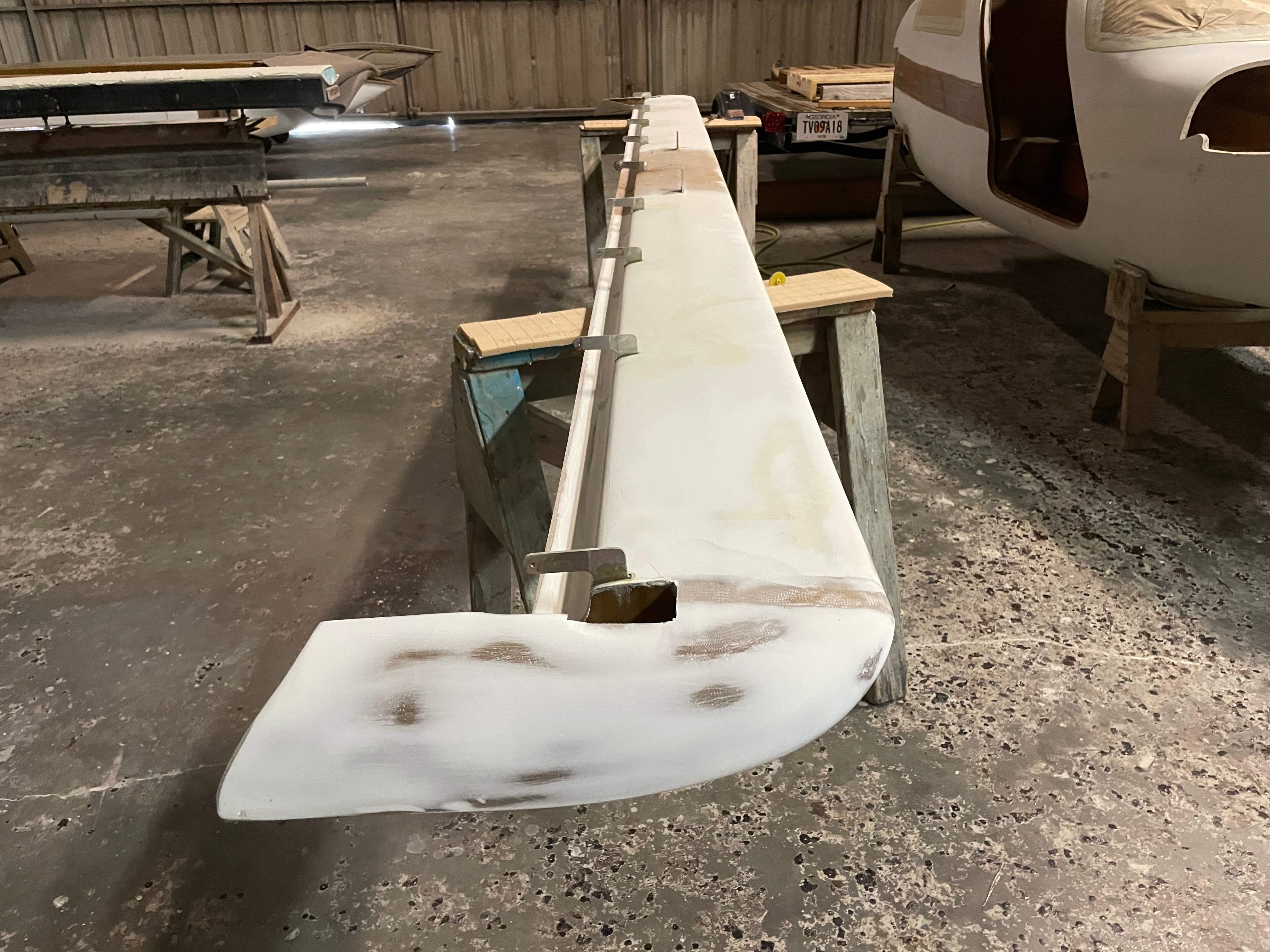
- Here the elevators are being installed and aligned to fit the canard shape. The canard and elevators are currently upside down.
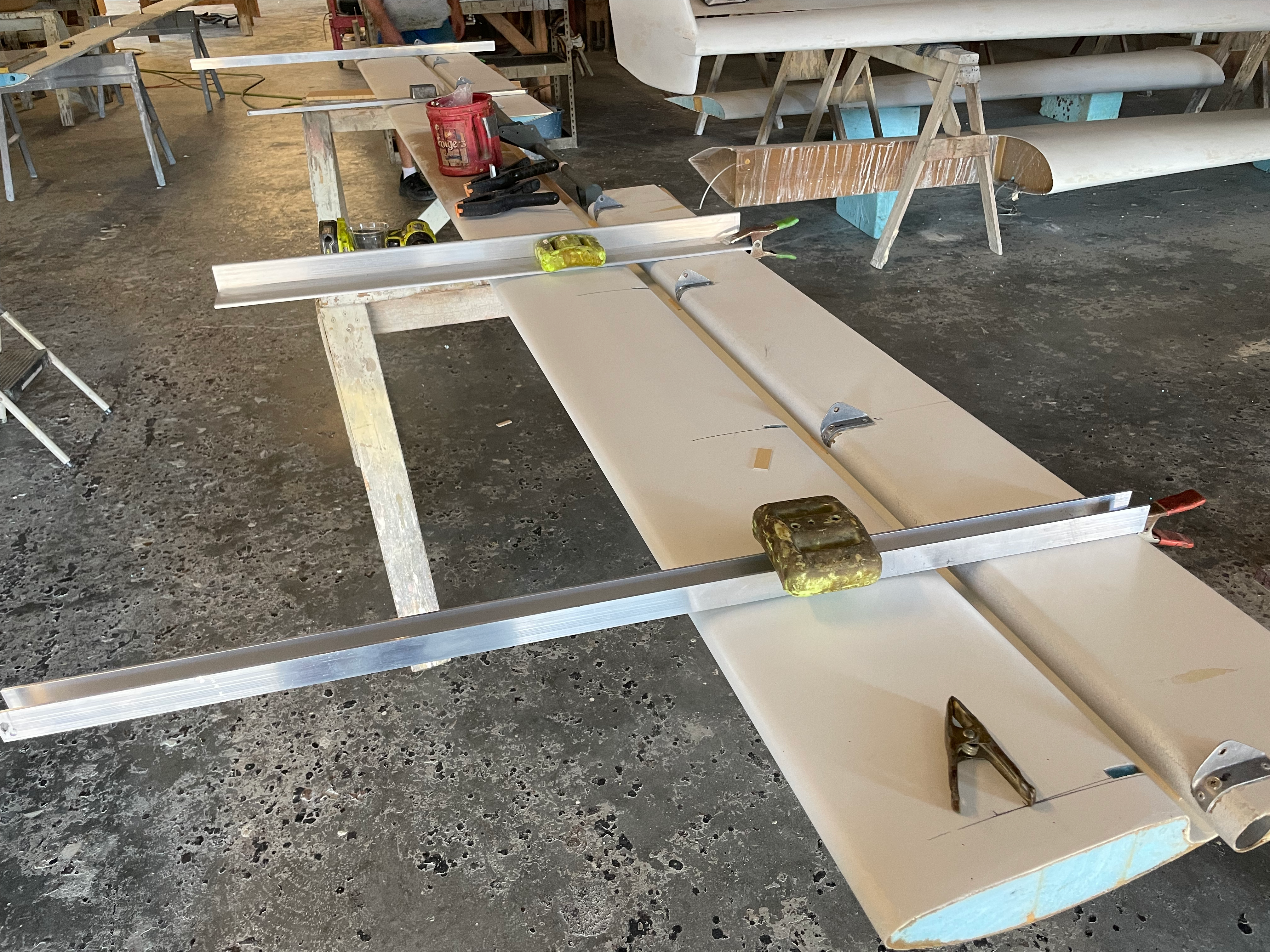
Canard Elevators
- Rudder cut out for additional glassing and work.
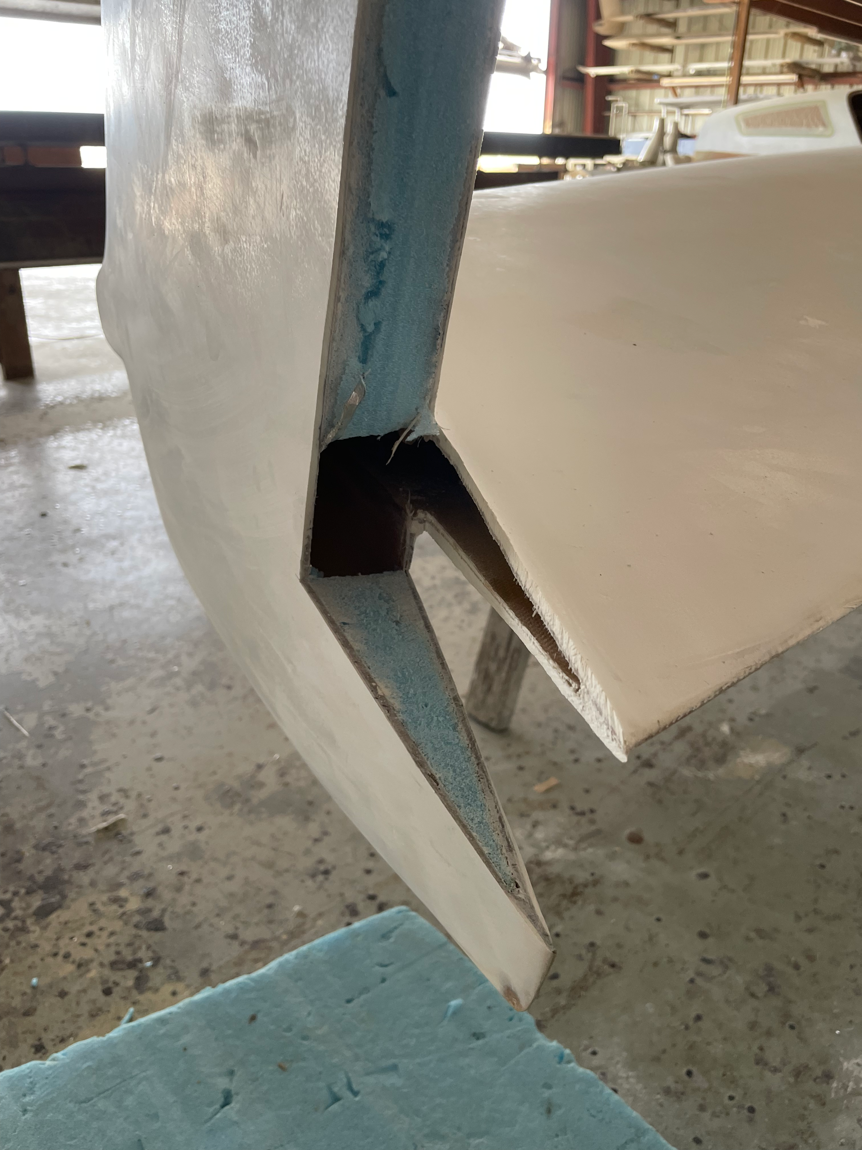
Rudder Cutout
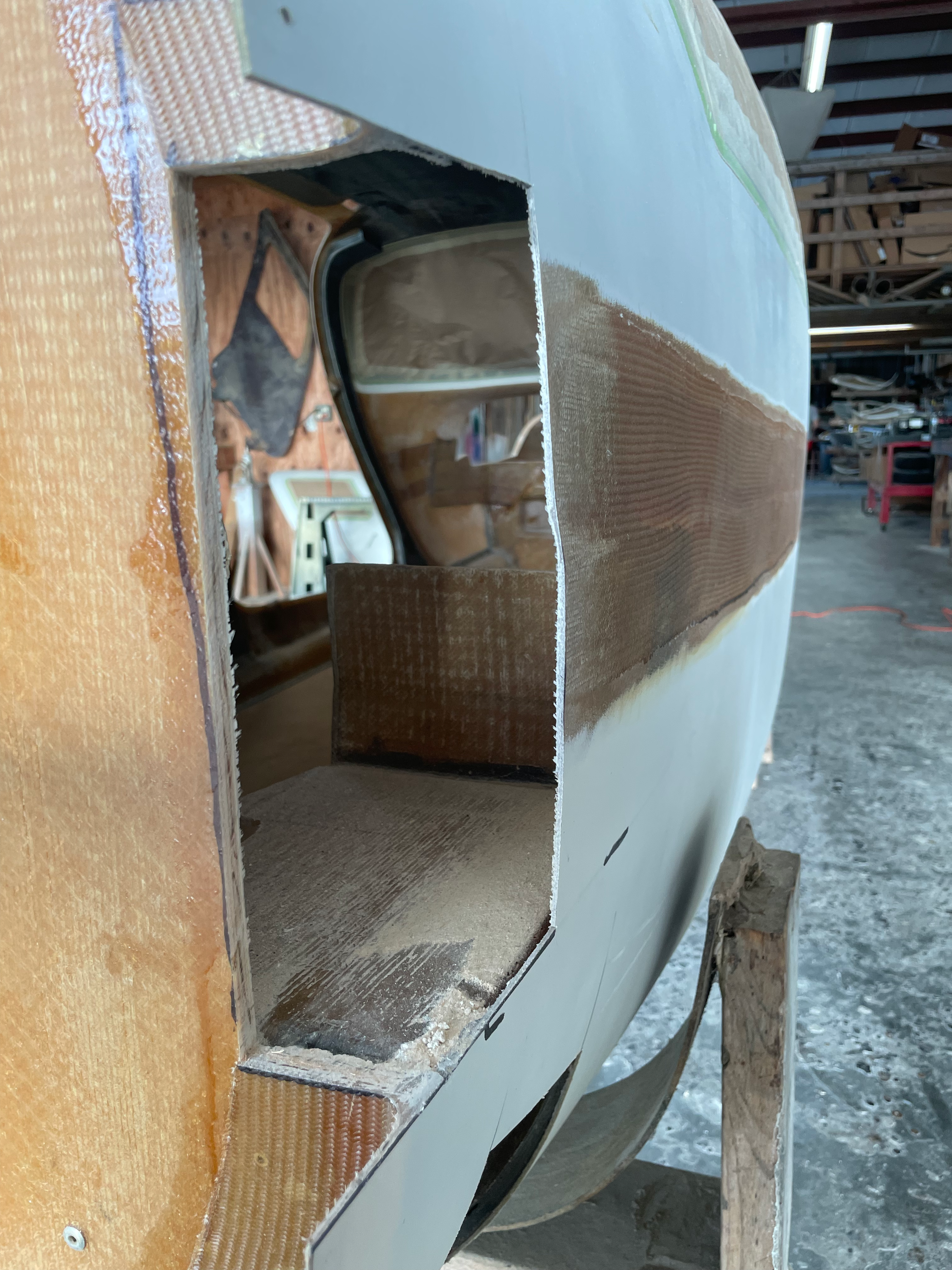
- Canard / Doghouse Cut out.
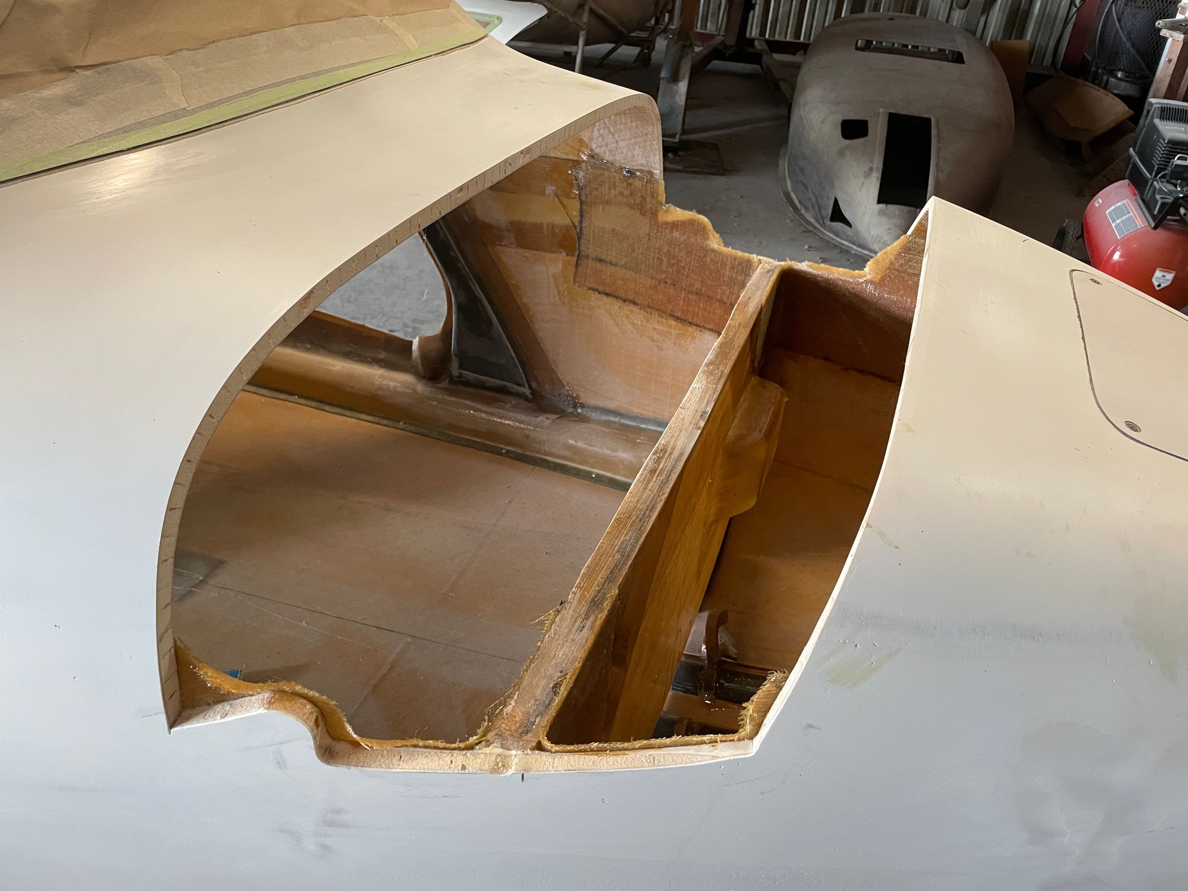
Canard Cutout
- Wing Tips being added to Canard.
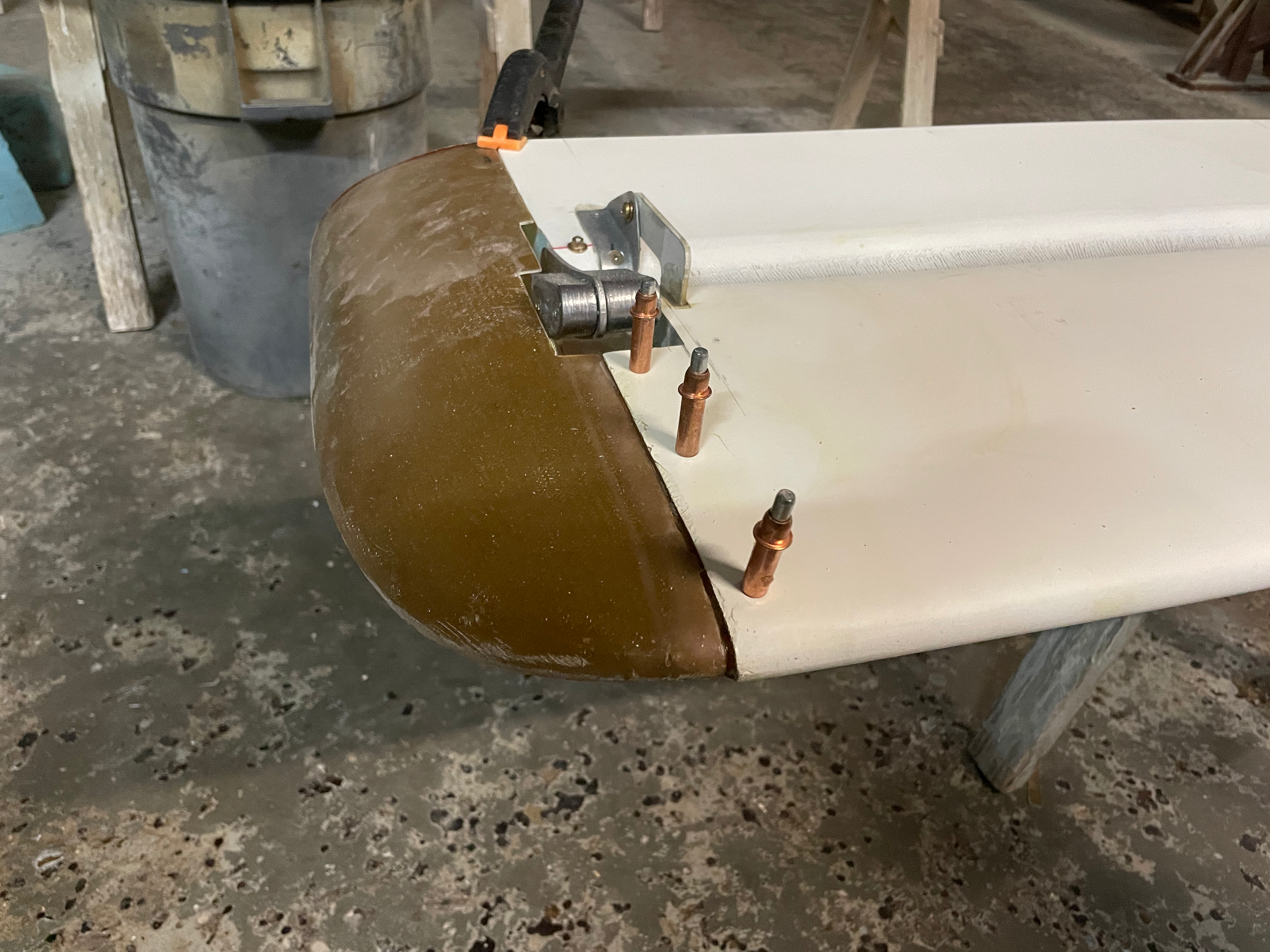
Wing Tips
- Rudder Conduit being glassed into place.
Rudder Conduit
- Landing gear hydraulic installed
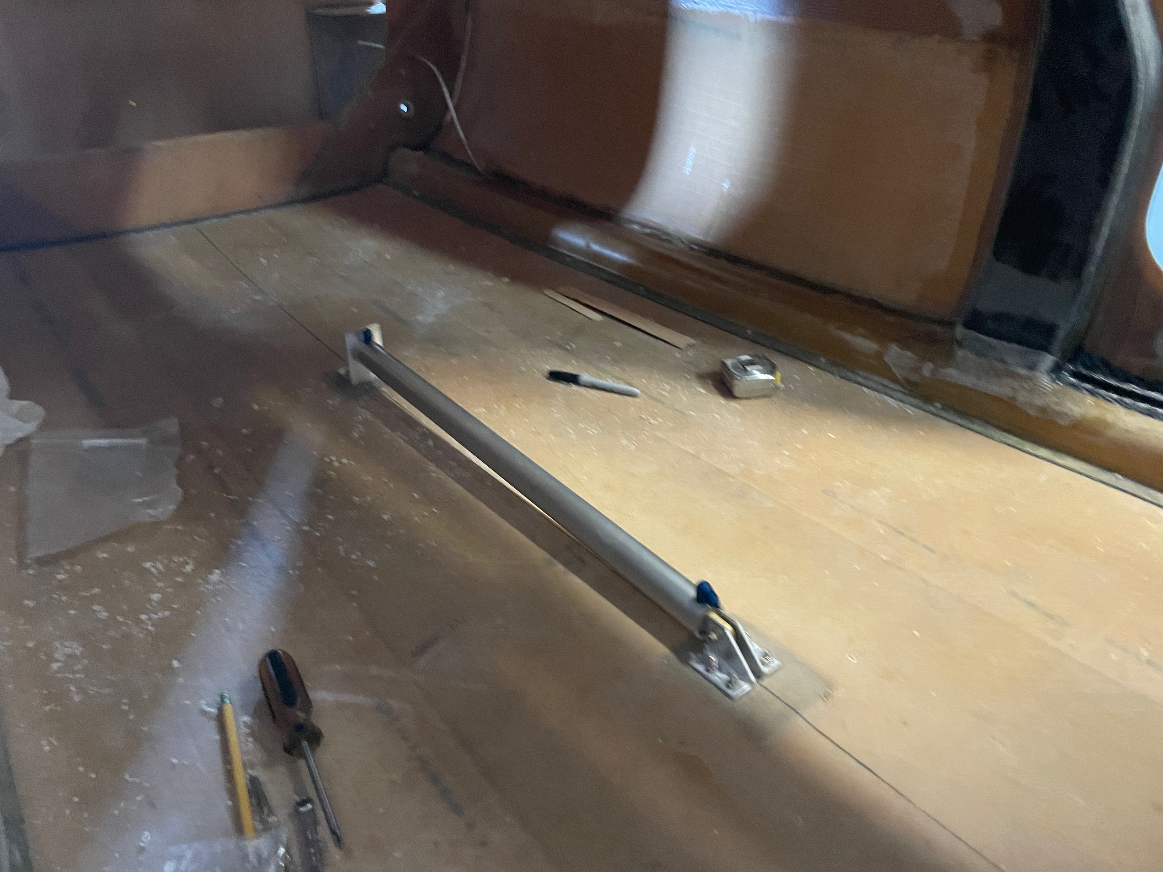
Landing gear hydraulic
- Keel Permanently installed
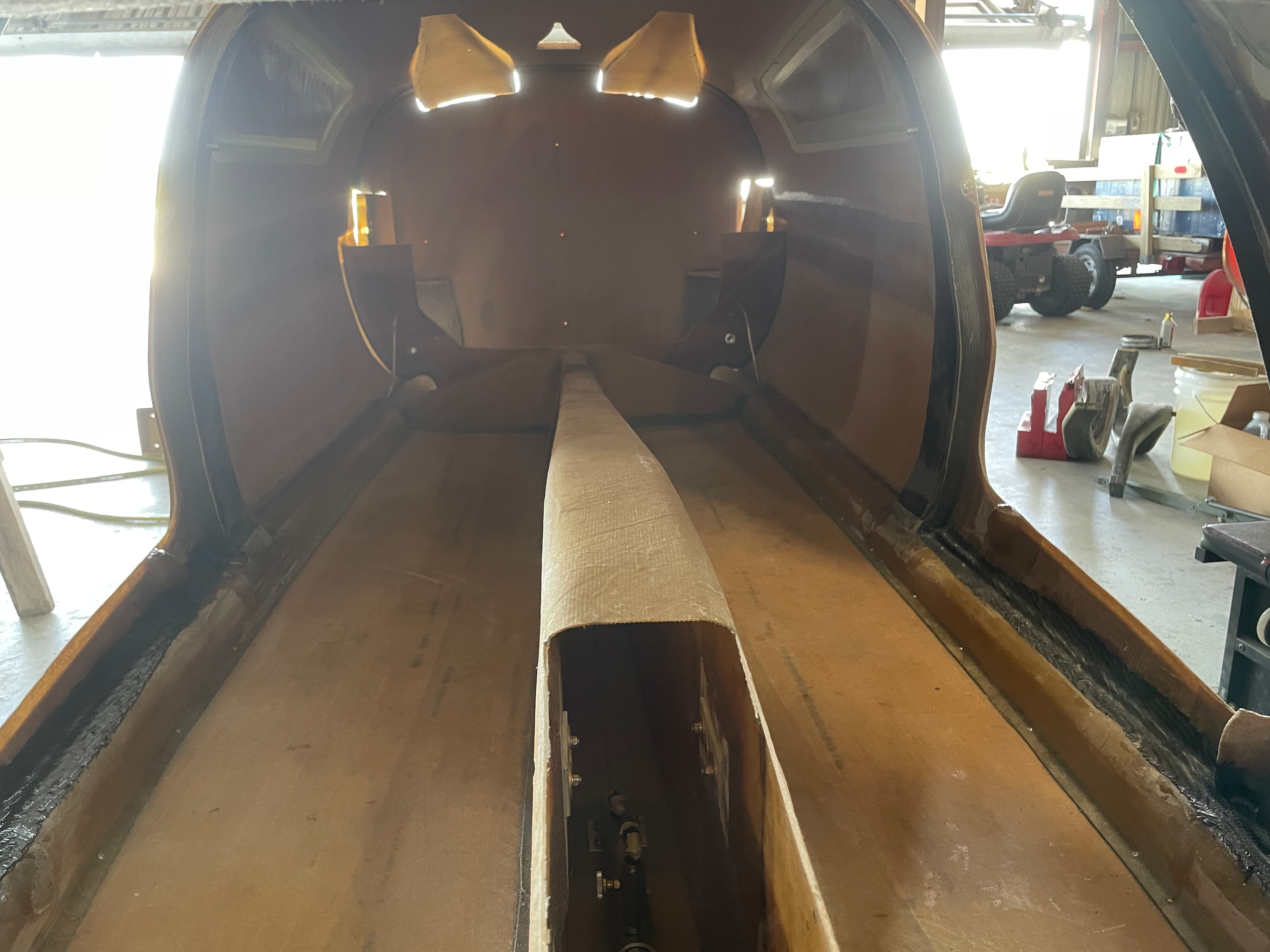
Keel Installed
- NACA ducts installed and holes for spar cut out.
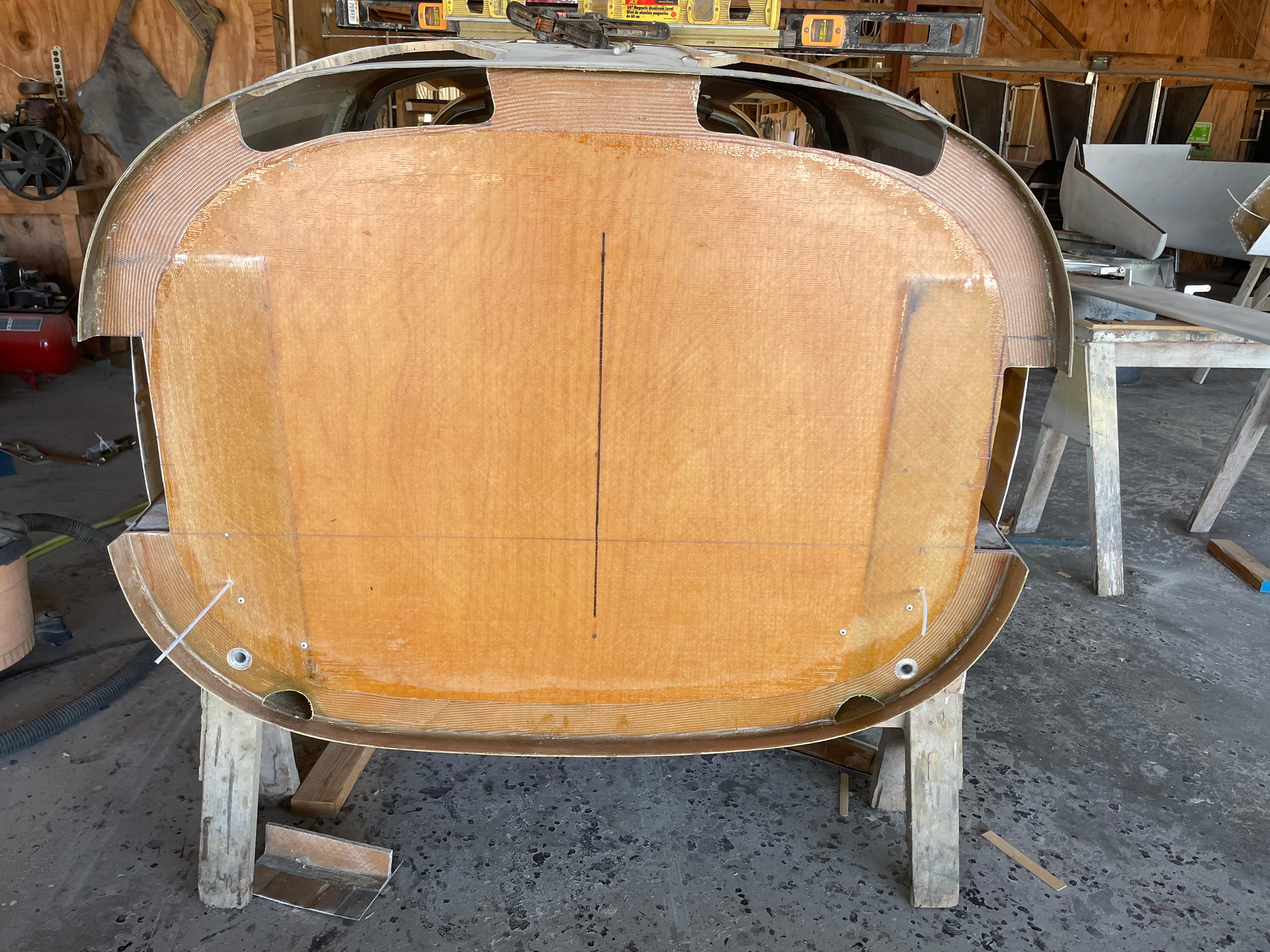
Rear View
- Wing tips skimmed and blended to canard.
Wing Tips skimmed
- Rudder internals being glassed.
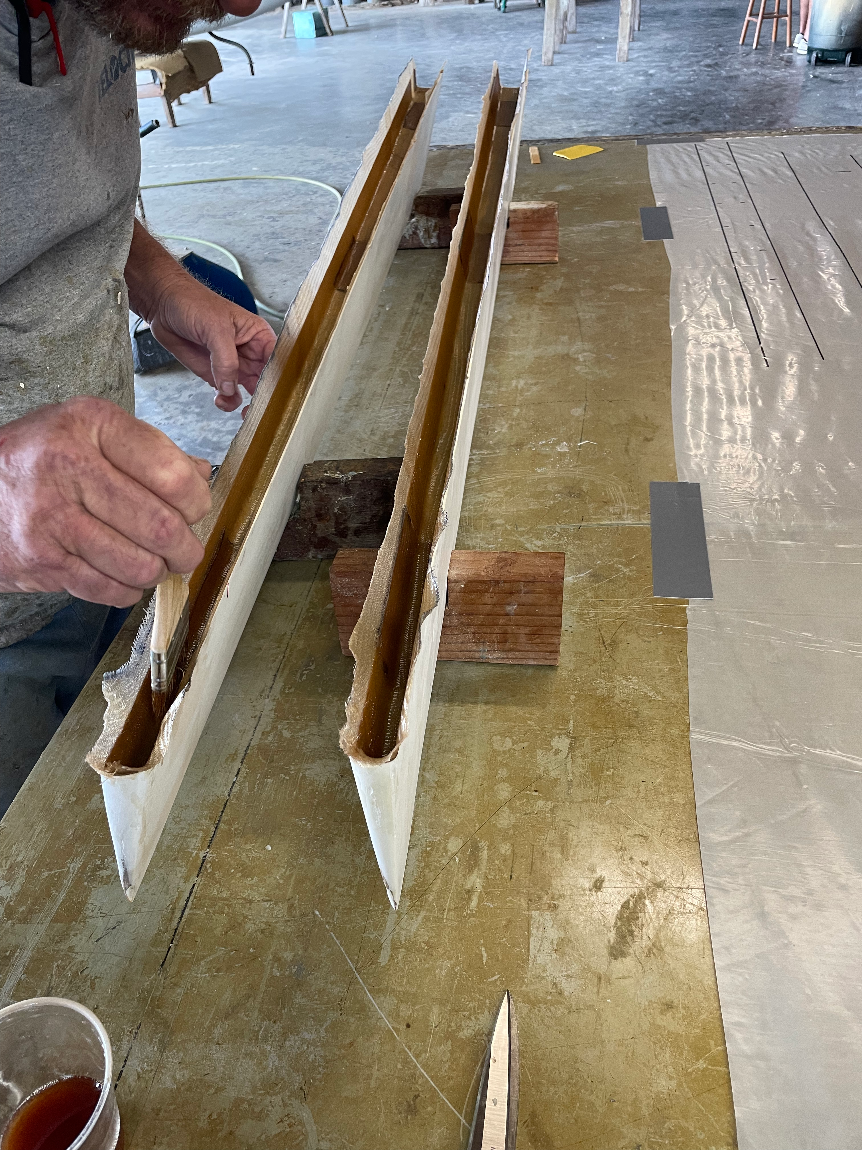
Rudder’s being glassed.
- Center Spar holes being cut.
Slots for center spar are cut
- All packed up
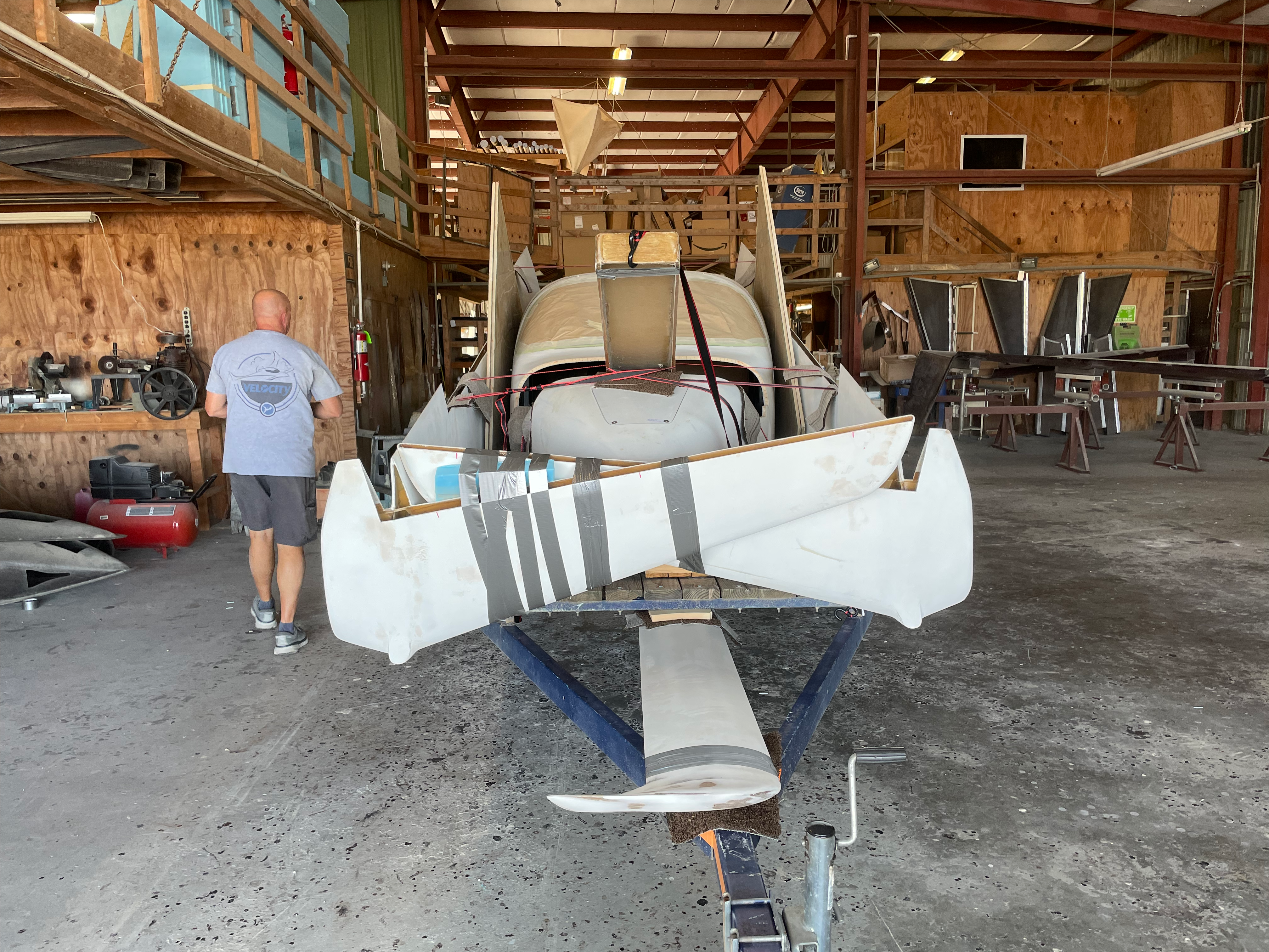
All loaded onto the trailer
The notes from the two weeks are lite as I chose to spend more time making and less time documenting.
The hope is that from here on in, notes should be more detailed as I will be in a position to work, photograph and document more.