Waves of Florida is a short podcast containing audio and video recorded in Jupiter Florida, USA.

Waves of Florida

Waves of Florida

Jupiter beach is a sandy beach that causes the waves to crash softly on the surf. It’s perfect as background audio for when you need to relax.
You can find an audio only clip here:

I also took some video footage at the beach and have uploaded it to YouTube here is the clip:

The Podcast page can be found at:

Waves of Florida

When I was very young. I had the vision I wanted to be a pilot.

It originally started with me wanting to join the Royal Navy to be a fast jet and helicopter pilot. However a few factor caused this dream to fall apart. For one, I was too tall and was told “It’s cheaper to find shorter people than to make bigger planes”.

Fast forward many years and eventually I achieved my goal of becoming a pilot.

The next adventure for me was to own an aircraft. While it wouldn’t make the cost of flying that much cheaper. It would give me the (emotional and physical) freedom to go on adventures anywhere and when I wanted to.

One of the biggest criterial I had was that the airplane needed to fit larger sports equipment. Think bikes and snowboard bags – these aren’t small items.

Big Luggage

I decided to go down the route of building a plane. 1) I wasn’t prepared to drop +1 Million USD for an aircraft 2) The lead time for anything is +24 months.

In the end I decided to build a Velocity Aircraft, its a pusher style aircraft with the engine in the back and a swept back wing design that doesn’t need flaps.

Velocity Aircraft


As part of my project, I opted to have the factory build my wings and fuselage as part of a program called ‘fast build’. This takes the pressure off me to build such vital components.

I also opted to take advantage of their ‘builder assist program’, where I spent two weeks at the factory learning some of processes such as fiber glass work and shaping/molding using composite materials.

Let me talk you though some of the areas I chose to focus on while at the factory.

  • Here is the fuselage preassembled as part of the fast build.

    Airplane Fuselage

    Airplane Fuselage

  • Here is the keel of the airplane removed so that additional material can be added to stiffen and reenforce the landing gear.

    Airplane Keel

    Airplane Keel

  • Rear legs for landing gear are removed to install brake lines.

    Landing Leg

    Landing Leg

  • Here the elevators are being installed and aligned to fit the canard shape. The canard and elevators are currently upside down.

    Canard and Elevators

    Canard Elevators

  • Rudder cut out for additional glassing and work.

    Rudder Cutout

    Rudder Cutout

  • Canard / Doghouse Cut out.

    Canard Cutout

    Canard Cutout

  • Wing Tips being added to Canard.

    WingTips

    Wing Tips

  • Rudder Conduit being glassed into place.

    Rudder Conduit

    Rudder Conduit

  • Landing gear hydraulic installed

    Landing gear hydraulic

    Landing gear hydraulic

  • Keel Permanently installed

    Keel Installed

    Keel Installed

  • NACA ducts installed and holes for spar cut out.

    Rear view

    Rear View

  • Wing tips skimmed and blended to canard.

    Wing Tips Skimmed

    Wing Tips skimmed

  • Rudder internals being glassed.

    Rudder's being glassed.

    Rudder’s being glassed.

  • Center Spar holes being cut.

    Slots for center spar are cut

    Slots for center spar are cut

  • All packed up

    All loaded onto the trailer

    All loaded onto the trailer

The notes from the two weeks are lite as I chose to spend more time making and less time documenting.
The hope is that from here on in, notes should be more detailed as I will be in a position to work, photograph and document more.

During construction I’ve found that the use of 3d printing of parts, tools and components has accelerated the build time and also increased the quality of the end result. 

Let me take you through a few parts that I’ve built so far. 

Radio Antenna Core Holder

All of the comm, nav and radio antennas used the the project are all fed through 3 ferrite cores that helps reduce the noise on the line. In the assembly manual they recommend that you use heat shrink tubing to secure each core to the line. However this does nothing to secure the cores to the body of the aircraft. 

What if something jabs or pulls at the core by accident. 

Enter printed component 1, a ferrite core holder that can be attached to wings, fuselages and any flat surface. It’s a two component design with identical top and base that clamshell together. 

Here’s the design in CAD:

Ferric Core Holder

Here’s final assembly of the radio antenna and part.

3D part being installed

3D part being installed

Thoughts and conclusions;

The part was intentionally made to be a block rather than rounded surfaces. 

I wanted something that could be easily printed with a single component you could reuse without having to print a top and a bottom. 

There is enough material, that if you sand and round the top block once you have everything fixed in place. 

The flat surface allows you to fix the base to a bulkhead or fuselage and if you wanted to you could glass over the top with minimal work. 

You can find a copy of the file here.

Landing Gear Hydraulic Line Holders

Both the aluminum and flexible hose lines for the landing gear always look smarter when they are tidy and can’t move around. 

I was lucky enough to get a tour of a Gulfstream jet where they opened some of the panels and I was wow’ed at how neat all the lines and connectors were. 

Inspired by what I saw I wanted to replicate the same level of quality in my build. 

When it came to installing the hydraulic lines in the aircraft, I knew I wanted to keep everything sharp and neat looking so I measured the diameter of the hoses and printed up a top/bottom design that can hold the lines to prevent movement keep everything looking sharp. 

Here’s the design in CAD:

Screen Shot 2022-01-28 at 8.53.55.png

Here is a small clip of the top and bottom mating.

Example parts mating.

Here’s an example of how the parts look when mated.

Here is the holder being used to secure the aluminum hydraulic lines in the forward bulkhead. 

3D Printed Hose Holder

3D Printed Hose Holder

As you can see, it’s a single component you can use for both top and bottom with a hole in the middle for a fastener. 

I’m big on multi use designs and hate having to design something that isn’t easy to use and easy to get going with. 

Not having to worry about if a part is the top or bottom of a component is a big timer saver. 

Thoughts and Conclusions 

The ability to keep the lines looking smart but also out of the way of other components means this was a double win. The hoses are secure and if anyone pops the lid to see what’s inside I hope they would be impressed with how neat everything is. 

As you can buy 3d filament in almost any color these days, its very easy to match the 3d printed parts to either the primary or secondary color of your aircraft so that all the parts match and that it looks like part of the build.

Overall I’m very enthused with the parts I’ve been able to make for the aircraft and I can’t wait to see what else I can design. 

I saw a few peoples projects using 3D printed parts for AC directional vents, which inspired me to see what else could be built with the printer.

If anyone has any parts they would like to see made or have any they want to show me I’d love to see what has been built!

This is part two of my series in building a VFR LED Sectional Map.
You can find part one here

In my last post I talked about how to build the hardware, gluing the sectional map to the picture frame, attaching the LED’s and wiring up the RaspberryPi.

This post focuses on the software component.
There are two parts to the software project here.

1. Getting the weather for the appropriate airports
2. Converting the weather conditions into an LED color and sending to the correct LED.

If you just need the code, GitHub here.

I chose to write this script in Python because of how easy it is to use RPi.GPIO to interface with the GPIO Pins on the RaspberryPi.
As mentioned, Im using a RaspberryPi Zero Wireless, I picked this unit for two reasons;

1. It’s low powered
2. It’s got wifi

In the GitHub repo you will find a Python Script called metarManager.py, this script is used to gather the METAR data and then update the LED’s based on the METAR report.

As each LED is a tricolor LED, I grouped them all together based on Airport and corresponding GPIO pins.
eg: ‘KPDK’:(19,21,23)
Is PDK Airport, with Red Pin 19, Green Pin 21 and Blue Pin 23.

For information on how to turn on/off LED’s using the GPIO, please see this guide.

For the weather API, I found this awesome weather service called avwx.rest, this service reads and returns tons of JSON data on an airport, including weather, runways and altimeter settings. Part of that response object is a value called ‘flight_rules’.

Side note – What are flight rules?
Flight rules are regulations and procedures adopted for flying aircraft in various conditions.
They come in two flavors: VFR and IFR.

Whats VFR?
VFR stands for visual flight rules, and the term refers to a set of rules created by the FAA for flight in VMC, or visual meteorological conditions.
VFR rules cover visibility requirements and cloud clearance criteria required to fly with visual reference to the ground and/or horizon. These visibility and cloud clearance requirements vary depending on the type of airspace you’re flying in, but they exist to ensure that pilots flying VFR don’t get caught up in the clouds and crash into each other.

Whats IFR?
IFR stands for instrument flight rules – the set of rules that govern aircraft that fly in IMC, or instrument meteorological conditions. In general terms, instrument flying means flying in the clouds. More specifically, IMC is defined as weather that is “below the minimums prescribed for flight under Visual Flight Rules.”

It’s called instrument flight because the pilot navigates only by reference to the instruments in the aircraft cockpit. Flying in the clouds (IMC) requires an IFR flight plan and an instrument rating.

In some online services such as skyvector and foreflight they blend maps and visual information to help pilots get an accurate picture of what’s going on in the area.
See example:

ATL Sectional

All Green Means good flying

In these cases, colors are also used to help identify maps and visual information.

Green for VFR rules
Blue for Marginal VFR rules
Red for IFR rules
Purple for Marginal IFR rules (this is usually REALLY bad weather!)

As you can see from the image, Atlanta is in the green today which means it’s a great day to go flying.
By reading the flight rules property from the API, we can quickly pair the appropriate color on the LED.

Using simpleJSON paired with Python’s URL Library I wrote a function that can get METAR data on each airport in my array and return back the flight rules.

def getMetar(airportCode):
url = 'https://avwx.rest/api/metar/'+airportCode+'?format=json'
hdr = { 'Authorization' : apiKey }

try:
metarRequest = urllib.request.Request(url, headers=hdr)
response = urllib.request.urlopen(metarRequest)
metarResponse = response.read().decode('utf-8')
jsonMetar = json.loads(metarResponse)

if jsonMetar['flight_rules'] == 'VFR':
flightRulesObject[airportCode] = 'GREEN'

if jsonMetar['flight_rules'] == 'MVFR':
flightRulesObject[airportCode] = 'BLUE'

if jsonMetar['flight_rules'] == 'IFR':
flightRulesObject[airportCode] = 'RED'

if jsonMetar['flight_rules'] == 'LIFR':
flightRulesObject[airportCode] = 'PURPLE'

# flightRulesObject[airportCode] = jsonMetar['flight_rules']

if len(flightRulesObject) == len(ledPins):
# print(flightRulesObject)
updateLEDsFromMETARs()

except e:
print(e)
flightRulesObject[airportCode] = 'OFF'

You can see here that the function injects the correct airport code into the URL then makes the request.
Once it has its response we add all the data to the flight rules object and call the function to update the LED’s.

Once the colors on the LED’s are updated, I sleep the unit for 55 mins then run a cron job to reopen the script again on the hour, as METAR information is updated hourly this will keep the LED’s up to date with the latest weather.

You can find part two of this series here.

VFR Sectional LED Map

In the years I’ve been learning to fly a plane, two things always come up;

1. Whats the METAR (weather)
2. How does it effect the VFR Sectional (map)

Learning to read both the weather and maps for flying is an essential part of learning to fly a plane.

1. You need to know where you are going
2. You need to make sure you don’t fly into a thunderstorm…

Once I started to accumulate a few maps, I thought I would make good use of them by creating a fun, fast and visually appealing way to read the weather at a few airports around my local area.


Finding some very fancy (and cheap) frames from Michaels, I cut out and glued the sectional to the backboard and then drilled out the holes for the airports I wanted to light up.

For this project I decided to go for 5 Tri-Color LED’s, these were all wired up with the common pin to ground and the Red, Green and Blue LED’s to the RaspberryPi GPIO Pins.

Whats needed for this project
To get started on this project you are going to need:
1. VFR Sectional Map of the area you want
2. Picture Frame
3. RaspberryPi, I chose to use a RaspberryPi Zero Wireless here
4. Tri-Color LED’s
5. Some wires and some hot glue.

First off, identify what airports you want to get information on, then measure and cut your wires.. Tragically I failed to do this (so learn from my mistake) and so you can see from the pictures that some of the wires are a lot tighter than they should really be.

*Pro Tip*
I highly recommend getting a 90 Degree header for the RaspberryPi, that way your wires and pins will be more flush with the picture frame rather than sticking out. If I were to do this project again, hands down I would grab some from eBay or Amazon.

Once you have your map and are happy with what airports you want to light up, go ahead and cut the rest of the map away and glue the paper to the backboard.
I used PVA glue, but really any glue suitable for paper will be great here.

With the glue dry I then attached the LED’s, RaspberryPi and USB Power cable.
VFR Pi and Wires

VFR Pi

At this point the hardware is done and it looks like this:
VFR Sectional Front

Time to move onto the software! You can find part two of this post here

This guide focus is on installing open-vm-tools on Ubuntu based OS’s.

During the downtime of Christmas 2020, I wanted take some time to focus on some new and exciting changes in the virtual hosting world.
Namely the adoption of VMWare’s ESXI port onto the ARM architecture and the now ability to install VMWare ESXI 7.0 onto a RaspberryPi!

I won’t go into all the details on this port, but the crucks of it are around power and flexibility. With the port to ARM based processors, you can run ESXI on some beast processors such as ‘Ampere Altra Q80-33 80-core Arm CPU‘ but also on a home lab using a RaspberryPi4 with 8GB of Ram.

There are a number of guides to help you get setup with ESXI on your RaspberryPi, my favorite being this YouTube video by NetworkChuck.

Once you have a working VM one of the next jobs to do is to install the VMware Tools that link the virtual machine to the ESXI Host.
Normally you would just run command

sudo apt-get install open-vm-tools

However if you have stumbled upon this page, it likely means you have ended up seeing error:

Reading package lists... Done
Building dependency tree
Reading state information... Done
Package open-vm-tools is not available, but is referred to by another package.
This may mean that the package is missing, has been obsoleted, or
is only available from another source

Which looks like this in a terminal window:

VM Install Error

Wamp Wamp. After a long peruse of the worlds favorite search engine:

Google History

Google History

I found nothing that would help.

But! I did find the git repo to VM’s tools. GitHub VM Repo.

So here is the Jan 4th 2021 Guide to installing VMware Tools onto Ubuntu ARM OS’s that are hosted on a RaspberryPi ESXI Host.

  • ssh into your virtual machine, if your setup is anything like mine it will be:ssh [email protected]

    Once you provide a password and are at the terminal, issue the following command

    sudo apt install -y git automake make gobjc++ libtool pkg-config libmspack-dev libglib2.0-dev libpam0g-dev libssl-dev libxml2-dev libxmlsec1-dev libx11-dev libxext-dev libxinerama-dev libxi-dev libxrender-dev libxrandr-dev libxtst-dev libgdk-pixbuf2.0-dev libgtk-3-dev libgtkmm-3.0-dev

This will install any needed toolchains and compilers.

Then if you aren’t already at your /home directory, run command
cd ~
This will take you home and give us a location to clone the VM tools directory to.

Now, lets grab the VM Tools from the above repo.

git clone https://github.com/vmware/open-vm-tools.git

Once downloaded, lets jump into the main directory and start to set things up.

cd open-vm-tools/open-vm-tools/

First thing we need to do is run the config on the dir, then issue the make and make install commands.
Its important to run these as either root or sudo, you can do this by either running command sudo su or adding sudo to each line.

sudo su
autoreconf -i
./configure --disable-dependency-tracking
make
make install
ldconfig

Next we need to make a vmtoolsd.service file, using your favorite text editor (Go Nano!) create a file called vmtoolsd.service in directory: /etc/systemd/system/

you will need to run this as a sudo or admin user: sudo nano /etc/systemd/system/vmtoolsd.service

In the file, copy and paste the following:

[Unit]
Description=Service for virtual machines hosted on VMware
Documentation=http://github.com/vmware/open-vm-tools
After=network-online.target

[Service]
ExecStart=/usr/local/bin/vmtoolsd
Restart=always
TimeoutStopSec=5

[Install]
WantedBy=multi-user.target

Save and exit the file and then issue the following commands:

sudo systemctl enable vmtoolsd.service
sudo systemctl start vmtoolsd.service

Boom! You can now verify that your VM has the tools installed by doing a quick command:

sudo systemctl status vmtoolsd.service

But you can now also go to the VM UI window and the ESXI host will tell you if the service is working and has connected successfully.
VM Tools Installed

For those that just want a super fast and efficient copy and paste into your CLI, the following is what you need:

  • sudo apt install -y git automake make gobjc++ libtool pkg-config libmspack-dev libglib2.0-dev libpam0g-dev libssl-dev libxml2-dev libxmlsec1-dev libx11-dev libxext-dev libxinerama-dev libxi-dev libxrender-dev libxrandr-dev libxtst-dev libgdk-pixbuf2.0-dev libgtk-3-dev libgtkmm-3.0-dev && cd ~ && sudo git clone https://github.com/vmware/open-vm-tools.git && cd open-vm-tools/open-vm-tools/ && sudo autoreconf -i && sudo ./configure --disable-dependency-tracking && sudo make && sudo make install && sudo ldconfig
  • then:

  • sudo nano /etc/systemd/system/vmtoolsd.service
  • copy and paste:

    [Unit]
    Description=Service for virtual machines hosted on VMware
    Documentation=http://github.com/vmware/open-vm-tools
    After=network-online.target

    [Service]
    ExecStart=/usr/local/bin/vmtoolsd
    Restart=always
    TimeoutStopSec=5

    [Install]
    WantedBy=multi-user.target

    then:

  • sudo systemctl enable vmtoolsd.service && sudo systemctl start vmtoolsd.service
  • For Christmas this year I received a few nerdy toys; One of them being a digital power meter (Amazon Link) that allows you to see your energy consumption.

    I mainly asked for it so that I could start tracking energy usage around the house. Mostly for fun and only partially for the data.

    After watching a number of videos on YouTube all about Tesla PowerWalls and the app that comes with it, I got inspired to build a similar kind of app / utility monitor to allow me to see how much power the house consumes and when are my peak energy consumption times.

    This post primarily focuses on getting the data from the Modbus power meter into a RaspberryPi. Separate posts will include building services to publish this data.

    There are two options to buy the power meter; A lcd display unit that gives you a quick read out and a unit that converts its signals into Modbus RS485 which can then be plugged into a bigger system – in my case a RaspberryPi. (Clicking on the images takes you to Amazon, it’s not an affiliate link. I’m just being helpful if you want to copy my setup).

    Power Meter with LCD Screen

    This power meter gives you an instant read out of energy consumed.

    This power meter outputs its energy readings using the Modbus RS485 Protocol

    This power meter outputs its energy readings using the Modbus RS485 Protocol

    The reason that I chose to use the Modbus power meter rather than the LCD was that I wanted to measure power coming into the house from my circuit breaker and while its great to quickly wire the LCD unit into the setup, running around the house and then back to the circuit breaker would have just been too boring.. plus code!

    Here’s a simple setup digram for how I wired the power meter into my house electrical system.

    Electrical Wiring Diagram

    Both the live and neutral are wired into the power meter and then the inductor is placed to encapsulate the live wire.

    !* ⚠️ Warning! ⚠️ *!
    Electricity is VERY dangerous, please take every precaution you can to be safe. If in doubt consult a qualified electrician who can do the work for you.

    Depending on the setup and country your going to get a few outputs of power.
    In the US, power is 110/220AC at 60Hz, in the UK its 240AC at 50Hz, in Europe its 230AC at 50Hz. Again, please consult a qualified electrician for your region, the last thing anyone needs is to short a wire and burn your house down.


    Once you have the power meter wired up you can begin to take some measurements. The unit maker PeaceFair have released a windows version to read the values quickly. You can find a link here; however it requires an AliExpress login. If you’re using windows and don’t need anything more a viewer this is probably going to be perfect for you.


    In my setup I’ve plugged the USB connector into a RaspberryPi, the Pi using the latest version of Raspbian Buster Lite. Buster Lite is a variant of Ubuntu and so you can run ubuntu commands.

    First thing to do is to update the Pi’s software.

    sudo apt-get update -y && sudo apt-get upgrade -y


    This updates all the installed software on the Pi and allows us to start with a fresh up-to-date image.

    In the user Pi home directory create a new folder called powerMeter.

    cd ~ && mkdir powerMeter && cd powerMeter

    This command will create the folder and navigate to it.

     
    Once here, we need to setup a Python script to communicate with the power meter.

    The power meter uses a protocol called ‘Modbus‘ which was invented in the late 1970’s and uses two wires to communicate between a master and multiple slave devices on the same 2 wire network. Its protocol is very similar to RS232 only with less device handshaking.

    Due to the open nature of Modbus, a number of tools and scripts exist to communicate with a Modbus device.

    For Python, I’m going to be using the ‘MinimalModbus library which will do a lot of the heavy lifting for us.


    To get started create a script called ‘powerMeter.py‘ using your preferred text editor. Im using nano, but feel free to use vim or anything else.

    nano powerMeter.py


    Once in the text editor add the python3 shebang (The shebang line in any script determines the script’s ability to be executed like a standalone executable)

    #!/usr/bin/env python3

    Then import the needed libraries.

    import minimalmodbus
    import serial

    in this script the needed libraries are minimalmodbus and serial.


    Once we have setup the script we can start to define our powerMeter, adding in the needed credentials to make a connection via RS485/Modbus.


    powerMeter = minimalmodbus.Instrument('/dev/ttyUSB0', 1)
    powerMeter.serial.baudrate = 9600
    powerMeter.serial.bytesize = 8
    powerMeter.serial.parity = serial.PARITY_NONE
    powerMeter.serial.stopbits = 1
    powerMeter.mode = minimalmodbus.MODE_RTU
    print('Details of the power meter are:')
    print(powerMeter)


    Let’s unpack what’s going on here; powerMeter is the object that’s been created to act as the connection via the USB socket (‘ttyUSB0’), the 9600 refers to the speed of communication. At the end the RTU mode sets up the specific protocol that the service will use. Modbus actually has a few different ones, so we need to implicitly define one.

    At the end, the powerMeter is printed to show what values have been assigned.

     
    Now that the powerMeter has been created, a function can be created to read the data values from it.


    def readPowerMeter():
    print("Attempting to read power meter")
    try:
    voltageReading = powerMeter.read_register(0, 0, 4)
    ampsReading = powerMeter.read_register(1, 0, 4)
    wattsReading = powerMeter.read_register(3, 0, 4)
    frequencyReading = powerMeter.read_register(7, 0, 4)
    print("Voltage", voltageReading/10)
    print("Amps", ampsReading/10)
    print("Watts", wattsReading/10)
    print("Frequency", frequencyReading/10)
    except IOError:
    print("Failed to read from instrument")

    Finally call the function to read the values from the powerMeter function

    # Run the function to read the power meter.
    readPowerMeter()


    You can run the script by typing

    python3 powerMeter.py

    On success the script will print out all the values it could read from the meter.

    Here’s a copy of mine:

     
    Attempting to read power meter
    Voltage 245.7
    Amps 165.8
    Watts 329.3
    Frequency 60.0

    As you can see from the readouts, my house operates at 250AC (ish) Volts, I’m currently drawing 165 AMPS of power and consuming 329 watts of electricity.

    Success!

    Success!

    Success!

    With the basic script setup we can now make requests to the Modbus power meter and read back basic values about power being consumed in the house.
    Later posts will show how you can turn this data into information I can store on a server and then recall to a UI.
    Thank you!

    Attributes: 

    I placed a full copy of the script on GitHub. Please clone and use as you please!

    Community post which contained code I used in my setup – Thanks to Bill Thomson for sharing!.


    Ngrok – pronouce ‘en-grok’ is a fantastic bit of software produced by inconshreveable. The software lets you build temporary tunnels for your apps and development servers to the internet.

    It generates an internet addressable endpoint that then forwards onto your app/service behind a firewall.

    Over the last few years Ive relied on ngrok for everything from demo events used on stage to development work when I’ve needed to debug my project against real world internet services.

    Due to the cheapness and ease of setup, I now use a (lot of) RaspberryPi for most of my app development inside my home network.

    This post will help you setup ngrok on a RaspberryPi.

    First load up your terminal, on a mac you can find this in the applications folder or simple ask Siri to open a new terminal window.

    Once a new window is open you can then connect to the Pi. An example SSH command is

    ssh [email protected]

    Where pi is the user I want to connect as, and 192.168.1.10 is the IP address of the RaspberryPi itself.

    For more details on ssh’ing into a PI, please read the official documentation provided by the RaspberryPi team.

    Once you are connected to the Pi its always a good idea to update the Pi software, you can do this by:

    sudo apt-get update -y && sudo apt-get upgrade -y

    This will get you up to date with the latest software and ready to install anything new.

    Change directories into the root temp directory by:

    cd /tmp/

    The tmp directory is used by the system to store files that will be cleaned up at a later point, its a perfect spot for us to download our file to.

    We need to grab the latest URL for ngrok ARM from the downloads page on ngrok.com. Jump to the downloads page and copy the URL relevant to your hardware.

    If your using a newer RaspberryPi you can use the 64Bit edition

    Ngrok 64Bit


    Otherwise the regular ARM download will be what you will need.

    Ngrok Download


    The download link will look something like:

     https://bin.equinox.io/c/4VmDzA7iaHb/ngrok-stable-linux-arm.zip

    We can now download the latest stable NGROK from the server by issuing the wget command.

    wget https://bin.equinox.io/c/4VmDzA7iaHb/ngrok-stable-linux-arm.zip

    This will download the zipped file and store it in our tmp directory.

    Next we need to unzip the file. You can do this by issuing the unzip command.

    unzip ngro*

    You will notice here that I didn’t fill in the whole file name, Im using a wildcard to unpack everything that starts with ngro… This is because I placed the zipped file in the tmp directory there should only be one.

    With the application unzipped now, we can move it into the user ‘pi’ home directory by

    mv /tmp/ngrok ~/ngrok

    Once moved we can now jump into the pi directory

    cd ~

    The ~ symbol references the current user we are logged in as, in this case, its user pi.

    You can now test your ngrok app by issuing it a command, for example

    ./ngrok http 3000

    will create a HTTP and HTTPS tunnel that forwards traffic to port 3000 running on your RaspberryPi.

    I hope this (short) guide is helpful for when you need to test your app in the real world!

    Recently Twilio released a new product called Studio, which is a graphical drag and drop editor you can use to build workflows, IVR’s and bots – both via voice and SMS channels. Over the last little while, I’ve been using Studio to build some awesome bots.

    An awesome studio flow

    One of the bots that I have built is a blacklisting tool that prevents my apps from spamming and messaging unwanted users, this tool uses another product of Twilio called ‘functions’ which is essentially AWS Lambda but executed within the Twilio ecosystem.

    To do this project I found a great service called BanishBot, which dub’s itself as ‘An API designed to help you manage opt-in/out communications and access lists.’ In short, its an API you can use in distributed systems to manage your opt-in and out lists.

    In this post, I’m going to use Studio, Functions, and BanishBot to create an auto-updating opt-in/out application. At the end of the build, I’ll have a system where customers/people can automatically opt-in or out of my messages. I’ll then be able to use BanishBot in my application development as the last mile checker to make sure I’m not actually sending out unwanted messages.

    You’ll need the following to do this project:
    Twilio account (upgraded and with a phone number) – Sign up here
    BanishBot account – Sign up here

    Once your setup with your accounts, go into Twilio functions and create a new function using the blank template.
    Name the function something like ‘BanishNewNumber’, then copy and paste this code into the code field – update the username and APIKey fields with your own credentials.

    var banishbot = require(‘banishbot’);
    var username = ”; // Put your BanishBot username here
    var apiKey = ”; // Put your BanishBot API key here
    // This script is responsible for banishing a number to the banishbot platform
    // This script is usually initiated from a Studio function
    // and is passed the number that no longer wishes to be contacted.
    exports.handler = function(context, event, callback) {
    var numberToBanish = event.NumberToBanish;
    console.log(‘Stand back! Im going to Banish the number ‘+numberToBanish);

    banishPayload = {“banished”: true, “type”: “PhoneNumber”, “notes”: “STOP request from Studio Flow SMS StudioBot”}
    banishbot.banishNewItem(username, apiKey, numberToBanish, banishPayload).then(function(result) {
    // Success Result
    console.log(result);
    callback(null, ‘OK’);
    })
    .fail(function (error) {
    // Error Something died, here is the response
    console.log(error);
    callback(null, ‘OK’);
    });
    //callback(null, ‘OK’);
    };

    Once you have set this function up click save.
    Make the second function, called ‘UnbanishNumber’ then copy and paste this code into the code field – update the username and APIKey fields with your own credentials.

    var banishbot = require(‘banishbot’);
    var username = ”; // Put your BanishBot username here
    var apiKey = ”; // Put your BanishBot API key here
    // This script is responsible for unbanishing a number.
    // This is usually a request from a Studio flow to return SMS to a user.
    // This script updates the BanishBot Table to set the banished state to be false for a number.
    exports.handler = function(context, event, callback) {
    var numberToUnBanish = event.numberToUnBanish;
    console.log(‘Stand back! Im going unbanish ‘+numberToUnBanish);

    banishPayload = {
    banished: false,
    notes: ‘This number was un-banished using The BanishBot Studio Flow’
    };
    banishbot.updateBanishedItem(username, apiKey, numberToUnBanish, banishPayload).then(function(result) {
    // Success Result
    console.log(result);
    callback(null, ‘OK’);
    })
    .fail(function (error) {
    // Error Something died, here is the response
    console.log(error);
    callback(null, ‘OK’);
    });
    //callback(null, ‘OK’);
    };

    Great! A quick recap of the two functions we just created, one is responsible for banishing a number, and the other is responsible for un-banishing a number.

    Now let’s go ahead and create our Studio bot that will handle our inbound stop/start requests.

    But why build an opt-out bot?
    When engaging with consumers, customers or people via SMS you have to comply with carrier compliance requirements, industry standards, and applicable law.
    These often include the keywords HELP and STOP. In the case of shortcodes (five/six-digit numbers), you are also required to manage your own blacklist – something BanishBot is designed to do.

    This project is going to conform to the highest of standards, that is we are going to manage the following keywords:
    STOP, END, CANCEL, UNSUBSCRIBE, QUIT, HELP, INFO, START, and SUBSCRIBE

    I’m choosing to adhere to the highest of standards because it means I can use this project/code in a shortcode application without changing any code – handy!

    The keywords are broken down into three areas; Stop, Start and Help.
    When a user sends a message containing one of the STOP words (STOP, END, CANCEL, UNSUBSCRIBE, QUIT), we are going to banish this number.
    When a user sends a message containing one of the START words (START, and SUBSCRIBE), we are going un-banish the number.
    When a user sends a message containing one of the HELP words ( HELP, INFO) we are going to reply to the user with details on how they can get in touch – an email address or website for example.

    You can find more details on TCPA compliance and industry regulations here: https://support.twilio.com/hc/en-us/articles/223182208-Industry-standards-for-U-S-short-code-HELP-and-STOP

    From your Twilio console navigate to Studio and create a new flow, I’ve called mine ‘MatBot’ but feel I recommend you stick with a naming convention relevant to your project.

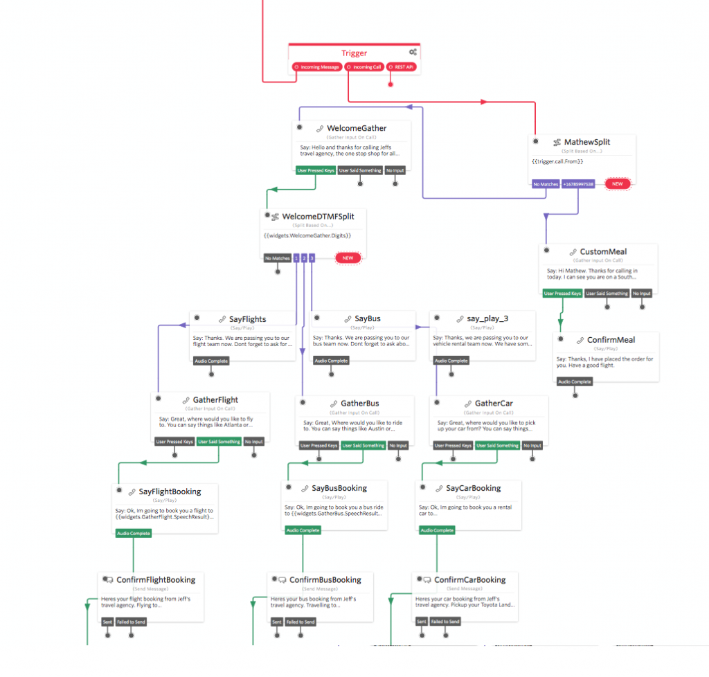
    Your new empty flow will contain just a red trigger box with three connectors attached, one for inbound messages, one for inbound calls and one for REST API requests.

    If you aren’t familiar with Studio have a look at the getting started pages.

    Today we will be focusing on the SMS opt-out mechanism.
    The first ‘widget’ we are going to drag onto the page is the ‘Spit’ Widget. A split is used to help guide how an application will react given different input parameters – in our case the SMS message body.
    Drag a split widget onto the flow and link it up to the inbound SMS trigger. It should look something like this:

    Message Split

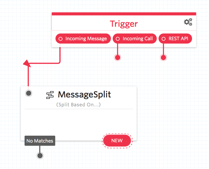
    Now when someone sends our number a message, we are going to parse that text and perform different responses based on the message body.

    Before we can add any connects let’s drag the rest of the components onto the flow and configure them.
    Drag a function widget onto the flow and name it ‘BanishThisNumber’, then from the function drop down select the function ‘BanishNewNumber’ and in the parameters section create a new parameter called ‘NumberToBanish’ with a value of ‘{{trigger.message.From}}’. The {{ brackets }} tells studio that this parameter is dynamic and to use the SenderID we received the message from.

    Once you have this widget setup save and then repeat the function setup, this time for the unbanish number function. I called mine ‘UnBanishThisNumber’ linking to function ‘UnbanishNumber’ passing a parameter called ‘numberToUnBanish’ with value ‘{{trigger.message.From}}’.

    Great! Now let’s add our first split, click the ‘New’ button, select ‘Regex’ from the drop down and in the value box type STOP. Once you have typed STOP a new drop-down will appear. From the drop-down select the function ‘BanishThisNumber’.

    Banish This Number

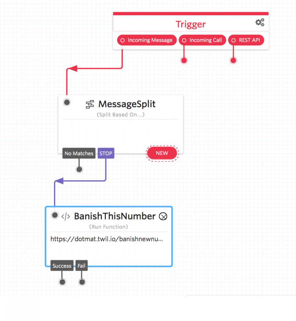
    Now when someone sends the message STOP to your number, the studio flow will route the message to the ‘BanishThisNumber’ function which will update the BanishBot service with this number which will now be banished. Now that you have one link setup lets connect the other opt-out keywords; END, CANCEL, UNSUBSCRIBE and QUIT.

    Now, this is great but what if a user wants to opt back into your service. To opt a user back in they need to send one of the following words; START or SUBSCRIBE. You can add these words the same way you added the STOP keywords but link the keywords to the function ‘UnBanishThisNumber’.

    Finally, we need to add support for the help/information keywords; HELP, INFO.
    For help and information, we can reply to the message with a response that directs the user to our helpdesk or email address.
    Drag a ‘Send Message’ Widget onto the flow and insert your response message.

    Your Studio flow should look something like this:

    BanishBot Studio Flow

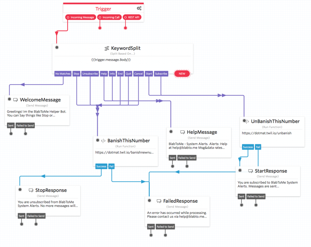
    Fantastic! Congratulations on building your opt-out bot!
    Now when anyone wants opt-out of your services they will be handled automatically by the studio flow.

    For the sending side, you now need to build BanishBot into your sending mechanism, so that each time you want to send someone an SMS message, the sending mechanism first checks the number against BanishBot and rejects the request if the number is indeed banished. – You can find the BanishBot Docs here, https://www.banishbot.com/docs.html
    Hope you have fun banishing things 😉

    An ever increasing problem in the digital age is the continual use and unwanted exposure of rude words and profanity. Thinking about this from a business perspective its never great when your customer service agents are exposed to an angry customer who does nothing but swear in a real time live chat.

    Lets take for example a (Twilio) SMS powered customer support channel.

    The standard work flow would be

    Raw Inbound Request

    Here the message comes into your support application, the raw content is added to a ticket or messaging system and is presented to your customer agent.

    If this inbound contains profanity or other rude words your agents are immediately exposed to this.


    Fortunately I’ve found a service that scans text bodies for rude words and replaces them – WebSanitize.

    Using WebSanitize you can implement a profanity filter at the server or application layer.

    This lets you build a workflow into your inbound messages process.

    In layman’s terms we can add a method to scan inbound messages for profanity and replace the words.

    This gives you the option of adding a layer between the rude inbound messages and our / your customer service agents.


    Getting started with WebSanitize

    The core of WebSanitize is fast API, to get started you need to sign up for an account with them. Once you have an API Key the request is fairly straight forward:

    To make a request you need to pass the following details:


    URL https://api.websanitize.com/message
    API Key Your API Key
    Content-type application/json
    filter ‘word’ or ‘character’
    message The message you want inspected


    An example API request would be:

    curl -XPOST -H ‘x-api-key: This1sN0tS3cure’ \
    -H “Content-type: application/json” \
    -d ‘{“filter”:”word”, “message”:”What the fuck man!”}’ \
    ‘https://api.websanitize.com/message’

    Here the message that needs to be inspected is: “What the fuck man!” and the API is going to perform a word swap if it finds any profanity.

    The response to the above request is:

    {
    “JobID”:”u4C9JTNPB3a8ykplhAi8YJyzXodGoF”,
    “MessageAlert”:true,
    “OriginalMessage”:”What the fuck man!”,
    “CleanerMessage”:”what the duck man!”
    }

    The return response contains

    JobID A unique ID for this request
    MessageAlert true/false if a banned word was found
    OriginalMessage The original unfiltered message
    CleanerMessage The cleaned message


    The first thing to notice is that ‘MessageAlert‘ flag has been set to true. You can use this as a first step to see if you need to replace the original text is to check this status. e.g.:

    if(MessageAlert == true){
    // Replace the original text using the returned variable CleanerMessage
    } else {
    // The original message did not contain any profanity
    }


    With this ‘Sanitized’ message replacing the original one we can present this to our customer support agent.

    Why use WebSanitize or any kind of screening service?
    It’s often said that a companies best asset is the people.
    If you think about the abuse and language thats occasionally used by irate people when they speak to customer service agents, any barrier or in this case a ‘Sanitizer’ that can shield an employee from those harsh words is always a good thing.
    Using a service like WebSanitize gives your customer service agents confidence that you or your organisation  are proactively taking steps to keep them safe and shielded from those undesirable words.