For Christmas this year I received a few nerdy toys; One of them being a digital power meter (Amazon Link) that allows you to see your energy consumption.

I mainly asked for it so that I could start tracking energy usage around the house. Mostly for fun and only partially for the data.

After watching a number of videos on YouTube all about Tesla PowerWalls and the app that comes with it, I got inspired to build a similar kind of app / utility monitor to allow me to see how much power the house consumes and when are my peak energy consumption times.

This post primarily focuses on getting the data from the Modbus power meter into a RaspberryPi. Separate posts will include building services to publish this data.

There are two options to buy the power meter; A lcd display unit that gives you a quick read out and a unit that converts its signals into Modbus RS485 which can then be plugged into a bigger system – in my case a RaspberryPi. (Clicking on the images takes you to Amazon, it’s not an affiliate link. I’m just being helpful if you want to copy my setup).

Power Meter with LCD Screen

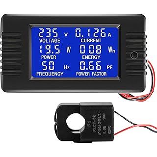
This power meter gives you an instant read out of energy consumed.

This power meter outputs its energy readings using the Modbus RS485 Protocol

This power meter outputs its energy readings using the Modbus RS485 Protocol

The reason that I chose to use the Modbus power meter rather than the LCD was that I wanted to measure power coming into the house from my circuit breaker and while its great to quickly wire the LCD unit into the setup, running around the house and then back to the circuit breaker would have just been too boring.. plus code!

Here’s a simple setup digram for how I wired the power meter into my house electrical system.

Electrical Wiring Diagram

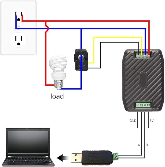
Both the live and neutral are wired into the power meter and then the inductor is placed to encapsulate the live wire.

!* ⚠️ Warning! ⚠️ *!
Electricity is VERY dangerous, please take every precaution you can to be safe. If in doubt consult a qualified electrician who can do the work for you.

Depending on the setup and country your going to get a few outputs of power.
In the US, power is 110/220AC at 60Hz, in the UK its 240AC at 50Hz, in Europe its 230AC at 50Hz. Again, please consult a qualified electrician for your region, the last thing anyone needs is to short a wire and burn your house down.


Once you have the power meter wired up you can begin to take some measurements. The unit maker PeaceFair have released a windows version to read the values quickly. You can find a link here; however it requires an AliExpress login. If you’re using windows and don’t need anything more a viewer this is probably going to be perfect for you.


In my setup I’ve plugged the USB connector into a RaspberryPi, the Pi using the latest version of Raspbian Buster Lite. Buster Lite is a variant of Ubuntu and so you can run ubuntu commands.

First thing to do is to update the Pi’s software.

sudo apt-get update -y && sudo apt-get upgrade -y


This updates all the installed software on the Pi and allows us to start with a fresh up-to-date image.

In the user Pi home directory create a new folder called powerMeter.

cd ~ && mkdir powerMeter && cd powerMeter

This command will create the folder and navigate to it.

 
Once here, we need to setup a Python script to communicate with the power meter.

The power meter uses a protocol called ‘Modbus‘ which was invented in the late 1970’s and uses two wires to communicate between a master and multiple slave devices on the same 2 wire network. Its protocol is very similar to RS232 only with less device handshaking.

Due to the open nature of Modbus, a number of tools and scripts exist to communicate with a Modbus device.

For Python, I’m going to be using the ‘MinimalModbus library which will do a lot of the heavy lifting for us.


To get started create a script called ‘powerMeter.py‘ using your preferred text editor. Im using nano, but feel free to use vim or anything else.

nano powerMeter.py


Once in the text editor add the python3 shebang (The shebang line in any script determines the script’s ability to be executed like a standalone executable)

#!/usr/bin/env python3

Then import the needed libraries.

import minimalmodbus
import serial

in this script the needed libraries are minimalmodbus and serial.


Once we have setup the script we can start to define our powerMeter, adding in the needed credentials to make a connection via RS485/Modbus.


powerMeter = minimalmodbus.Instrument('/dev/ttyUSB0', 1)
powerMeter.serial.baudrate = 9600
powerMeter.serial.bytesize = 8
powerMeter.serial.parity = serial.PARITY_NONE
powerMeter.serial.stopbits = 1
powerMeter.mode = minimalmodbus.MODE_RTU
print('Details of the power meter are:')
print(powerMeter)


Let’s unpack what’s going on here; powerMeter is the object that’s been created to act as the connection via the USB socket (‘ttyUSB0’), the 9600 refers to the speed of communication. At the end the RTU mode sets up the specific protocol that the service will use. Modbus actually has a few different ones, so we need to implicitly define one.

At the end, the powerMeter is printed to show what values have been assigned.

 
Now that the powerMeter has been created, a function can be created to read the data values from it.


def readPowerMeter():
print("Attempting to read power meter")
try:
voltageReading = powerMeter.read_register(0, 0, 4)
ampsReading = powerMeter.read_register(1, 0, 4)
wattsReading = powerMeter.read_register(3, 0, 4)
frequencyReading = powerMeter.read_register(7, 0, 4)
print("Voltage", voltageReading/10)
print("Amps", ampsReading/10)
print("Watts", wattsReading/10)
print("Frequency", frequencyReading/10)
except IOError:
print("Failed to read from instrument")

Finally call the function to read the values from the powerMeter function

# Run the function to read the power meter.
readPowerMeter()


You can run the script by typing

python3 powerMeter.py

On success the script will print out all the values it could read from the meter.

Here’s a copy of mine:

 
Attempting to read power meter
Voltage 245.7
Amps 165.8
Watts 329.3
Frequency 60.0

As you can see from the readouts, my house operates at 250AC (ish) Volts, I’m currently drawing 165 AMPS of power and consuming 329 watts of electricity.

Success!

Success!

Success!

With the basic script setup we can now make requests to the Modbus power meter and read back basic values about power being consumed in the house.
Later posts will show how you can turn this data into information I can store on a server and then recall to a UI.
Thank you!

Attributes: 

I placed a full copy of the script on GitHub. Please clone and use as you please!

Community post which contained code I used in my setup – Thanks to Bill Thomson for sharing!.


Ngrok – pronouce ‘en-grok’ is a fantastic bit of software produced by inconshreveable. The software lets you build temporary tunnels for your apps and development servers to the internet.

It generates an internet addressable endpoint that then forwards onto your app/service behind a firewall.

Over the last few years Ive relied on ngrok for everything from demo events used on stage to development work when I’ve needed to debug my project against real world internet services.

Due to the cheapness and ease of setup, I now use a (lot of) RaspberryPi for most of my app development inside my home network.

This post will help you setup ngrok on a RaspberryPi.

First load up your terminal, on a mac you can find this in the applications folder or simple ask Siri to open a new terminal window.

Once a new window is open you can then connect to the Pi. An example SSH command is

ssh [email protected]

Where pi is the user I want to connect as, and 192.168.1.10 is the IP address of the RaspberryPi itself.

For more details on ssh’ing into a PI, please read the official documentation provided by the RaspberryPi team.

Once you are connected to the Pi its always a good idea to update the Pi software, you can do this by:

sudo apt-get update -y && sudo apt-get upgrade -y

This will get you up to date with the latest software and ready to install anything new.

Change directories into the root temp directory by:

cd /tmp/

The tmp directory is used by the system to store files that will be cleaned up at a later point, its a perfect spot for us to download our file to.

We need to grab the latest URL for ngrok ARM from the downloads page on ngrok.com. Jump to the downloads page and copy the URL relevant to your hardware.

If your using a newer RaspberryPi you can use the 64Bit edition

Ngrok 64Bit


Otherwise the regular ARM download will be what you will need.

Ngrok Download


The download link will look something like:

 https://bin.equinox.io/c/4VmDzA7iaHb/ngrok-stable-linux-arm.zip

We can now download the latest stable NGROK from the server by issuing the wget command.

wget https://bin.equinox.io/c/4VmDzA7iaHb/ngrok-stable-linux-arm.zip

This will download the zipped file and store it in our tmp directory.

Next we need to unzip the file. You can do this by issuing the unzip command.

unzip ngro*

You will notice here that I didn’t fill in the whole file name, Im using a wildcard to unpack everything that starts with ngro… This is because I placed the zipped file in the tmp directory there should only be one.

With the application unzipped now, we can move it into the user ‘pi’ home directory by

mv /tmp/ngrok ~/ngrok

Once moved we can now jump into the pi directory

cd ~

The ~ symbol references the current user we are logged in as, in this case, its user pi.

You can now test your ngrok app by issuing it a command, for example

./ngrok http 3000

will create a HTTP and HTTPS tunnel that forwards traffic to port 3000 running on your RaspberryPi.

I hope this (short) guide is helpful for when you need to test your app in the real world!

So finally after many months of development, design, build, rebuild and writing of code. I have some data and information on my beehive! Its remarkable how much data you can get and learn about an environment by monitoring a few points over time. At the moment the BeeBetaBox is currently loading up, sending a HTTP  POST to an end point with lots of data about the beehive every 10 mins. This data is rolled into a database and then assembled together to generate graphs showing temperature over time Because I capture the GPS co-ordinates of the hive as well we can then use this to make a lookup against a weather service and provide the weather predictions for the next 3 days. Handy if your hive is remote and you want to see about a visit soon!

BeeSafe Graph

So after spending a considerable amount of time using Sakis – the 3G dongle software. I feel I need to write a better post on how to connect your Debian based system / Raspberry Pi to the internet using a 3G connection.

– Be warned, Data on the 3G network is RARELY all you can eat, ensure you have an appropriate data plan before you let your Pi loose.

– 2nd Warning.. 3G dongles consume huge quantities of power, if your running the project off a battery setup, write some code to disconnect the 3G stick when not in use to prevent it from eating all the power just staying connected.

With that being said, to download and install the 3G software:

sudo apt-get -y update

then

sudo apt-get -y upgrade

then

sudo apt-get -y install ppp

Once the updates have taken route and ppp has been installed you will need to download sakis;

wget “http://www.sakis3g.org/versions/latest/armv4t/sakis3g.gz”

then

gunzip sakis3g.gz

then

chmod +x sakis3g

finally

sudo ./sakis3g –interactive

This will take you to the interactive window used by Sakis, you can configure the 3G dongle here and then issue the connect command. The software has been set out to be easy to interact with.

Depending on the Simcard you have in the dongle, it may attempt to download the latest settings automatically and then offer them to you as a connection method.

If you don’t get that luxury you can manually enter your APN, username and password manually in the prompts.

One feature that I LOVE about Sakis is that you can call the connect command from within another program, lets say my Pi gathers some data up and then needs to send it somewhere on the net, you can tell the program to connect to Sakis like this:

./sakis3g connect APN=”CUSTOM_APN” CUSTOM_APN=”giffgaff.com” APN_USER=”giffgaff” APN_PASS=”password”

This string tells Sakis to connect to the Giffgaff network and can be followed by:

sudo ./sakis3g disconnect

How to add a custom APN to the sakis config file:
Using Nano create a file called sakis3g.conf stored in /etc/

sudo nano /etc/sakis3g.conf

Here you can add the APN details like this:

APN=CUSTOM_APN
CUSTOM_APN=”giffgaff.com”
APN_USER=”giffgaff”
APN_PASS=”password”

and then connect the 3G dongle by doing this:

sudo ./sakis3g connect

Super handy if you need to bring some 3G connectivity to your project! 🙂

With the PCB now built and soldered, my attention can turn to the software that powers the BeeSafe and the cloud API that it runs on.

The software is broken down into two parts; software run locally on each BeeSafe and software run in the cloud that manages all inputs, requests, alerts and data.

This post will focus on the software, hosted locally on the Raspberry Pi – the brain of each BeeSafe.

The focus of Raspberry Pi is to help teach people (children) the basics via Python (for more information visit: http://www.raspberrypi.org), so that is the language I have chosen to use on the Pi.

While the BeeSafe PCB has a variety of sensors (Temperature, GPS, Trip Switch and Accelerometer) the main one this post will focus on is temperature. On the board itself I have included a ds18b20 temperature sensor which uses the 1-wire thermal probe. Information on this can be found at: http://www.cl.cam.ac.uk/projects/raspberrypi/tutorials/temperature/ and http://learn.adafruit.com/adafruits-raspberry-pi-lesson-11-ds18b20-temperature-sensing/hardware

Once we have a powered and working Pi, we need to activate the 1-Wire probes, in the command line of your Pi type in :

sudo modprobe w1-gpio

then

sudo modprobe w1-therm

then

cd /sys/bus/w1/devices/

ls

On the page now you should have something that looks like:

w1_bus_master1 and another that looks like “28-000004bb8e9b“. The “28-000004bb8e9b” will be the serial number of the thermal probe, if you have more than one then, they should all be presented alongside each other.

You can directly interface with the thermal probe by typing in

cd /28-000004bb8e9b

and then

cat w1_slave

This will present you with a 2 line read out of data from the thermal probe, it should look something like:

19 01 4b 46 7f ff 07 10 eb : crc=eb YES

19 01 4b 46 7f ff 07 10 eb t=17562

From the output you can see a value called t=17562 which is the temperature but presented raw format, The actual value here is 17.562C. What we need is some code to read this temperature device and give us a useful temperature value.

The code found on the tutorial page at Cambridge (http://www.cl.cam.ac.uk/projects/raspberrypi/tutorials/temperature/) is a perfect starting point for building out with. A copy of the code is below:

# Open the file that we viewed earlier so that python can see what is in it. Replace the serial number as before.
tfile = open(“/sys/bus/w1/devices/YOURW1PROBE/w1_slave”)
# Read all of the text in the file.
text = tfile.read()
# Close the file now that the text has been read.
tfile.close()
# Split the text with new lines (\n) and select the second line.
secondline = text.split(“\n”)[1]
# Split the line into words, referring to the spaces, and select the 10th word (counting from 0).
temperaturedata = secondline.split(” “)[9]
# The first two characters are “t=”, so get rid of those and convert the temperature from a string to a number.
temperature = float(temperaturedata[2:])
# Put the decimal point in the right place and display it.
temperature = temperature / 1000
print temperature

Change to your user directory folder by:

cd ~

and open a new file by typing in:

sudo nano read_temp.py

Copy and paste the above code into the nano editor and be sure to change YOURW1PROBE to the serial number of your probe. If you saved this file as read_temp.py you can run it by typing in:

sudo python ./read_temp.py

it will read the thermal probe for data and print out the temperature in the correct format.. i.e. 17.562C not 17562

Now we can read real world temperature into our software! The next step is to install the libraries to allow us to send this data in an SMS message to our phones!

In your command line update APT using the following commands:

sudo apt-get update

sudo apt-get upgrade

Next we need to install PIP, this is done by:

sudo apt-get install python-pip python-dev build-essential
sudo pip install –upgrade pip
sudo pip install –upgrade virtualenv

and then

sudo pip install twilio

Twilio is a global voice and SMS API provider, they allow you to make & receive voice and SMS (as well as MMS) messages to and from phones to and web services. For this post we are particularly interested in the Sending SMS API which will allow us to send SMS messages from our local device to a cloud service to our mobile phone.

Twilio can be found online at: http://www.twilio.com

If you haven’t already done so, sign up for a trial account. You get $30 of credit to play with the Twilio system. Once you have signed up, you will need to buy a number (these cost $1 per calendar month, but will come out from the trial credit) and verify a phone number that you currently have (such as your mobile).

Once your signed up, in your account page you will need to note down your account SID and auth token. These can be found on the top of:  https://www.twilio.com/user/account

Now we need to start to form a more complex python code, fortunately we can build onto of the code we have written before! To maintain a logical evolution of our files we are going to make a copy of read_temp.py by typing in:

sudo cp ./read_temp.py ./send_sms_temp.py

This will make a copy of our read temp file and save it as send_sms_temp.py

Open up your text editor by typing:

sudo nano send_sms_temp.py

You should see an identical copy of the code we have written before; now we are going to modify this file so that it can assemble an SMS message from our temperature data.

Start by adding:

from twilio.rest import TwilioRestClient

to the top of the page, this will call the Twilio REST API client when the file loads.

Underneath the temperature code, we need to add the following lines:

account_sid = "ACXXXXXXXXXXXXXXXXX"
auth_token = "YYYYYYYYYYYYYYYYYY"
client = TwilioRestClient(account_sid, auth_token)
message = client.messages.create(to="+12316851234", from_="+15555555555",
body="Hello there! The temperature is: " + srt(temperature) + "c")
Substitute the account SID and auth tokens with the ones you wrote down from your user account page: https://www.twilio.com/user/account, then you will need to adjust the ‘to’ value to be a number you wish to SMS. Twilio uses international number standards, so a number in the United States would be ‘+14155555555’ and one from the UK would be ‘+447971234567’.
You will also have to adjust the ‘from’ variable to be the number you have provisioned when you signed up for your trial account. A word of warning, not all numbers from Twilio support SMS messages, particularly SMS messages across geographic locations.
To check which counties can receive messages from which number, check out: https://www.twilio.com/international – when you have signed up test your number works by sending yourself a message from your account portal  (https://www.twilio.com/user/account/developer-tools/api-explorer#POST/2010-04-01/Accounts/{AccountSid}/SMS/Messages.{format})
The srt(temperature) is us telling python to convert the numerical value of temperature into a string value so that it can be added to our outgoing SMS message. Strings and Strings go together, Numbers and Numbers go together, Strings and Numbers do not.
By now your code should look something like this:

from twilio.rest import TwilioRestClient

# Open the file that we viewed earlier so that python can see what is in it. Replace the serial number as before.
tfile = open(“/sys/bus/w1/devices/YOURW1PROBE/w1_slave”)
# Read all of the text in the file.
text = tfile.read()
# Close the file now that the text has been read.
tfile.close()
# Split the text with new lines (\n) and select the second line.
secondline = text.split(“\n”)[1]
# Split the line into words, referring to the spaces, and select the 10th word (counting from 0).
temperaturedata = secondline.split(” “)[9]
# The first two characters are “t=”, so get rid of those and convert the temperature from a string to a number.
temperature = float(temperaturedata[2:])
# Put the decimal point in the right place and display it.
temperature = temperature / 1000
print temperature

account_sid = “ACXXXXXXXXXXXXXXXXX” #Replace this with your account SID
auth_token = “YYYYYYYYYYYYYYYYYY” # Replace this with your auth token
client = TwilioRestClient(account_sid, auth_token)

message = client.messages.create(to=”+12316851234″, from_=”+15555555555″,
body=”Hello there! The temperature is: ” + srt(temperature) + “c”)

This is our complete SMS temperature application!

You should now be able to send yourself a temperature based SMS message by typing in:

sudo python ./send_sms_temp.py

Tada! If all has gone according to plan you should have sent yourself an SMS with the temperature your Raspberry Pi has read from the thermal probe.

How. Cool. Is. That!

Now that you have the basics, the world is your oyster. Imagine being sent a text message when your house is getting too cold. Or a morning message of the temperature outside before you leave the house. Or sending data from an SMS device into a database.. But thats another post..

After many (many!) attempts and learning’s.

Everything from PCB design via software, PCB manufacture via toner transfer and ensuring your board is soldered correctly has had to be designed, re-engineered and put into practice on almost a production line state of mind.

Finally the initial board is ready to rock!

Completed BeeSafe Board, Version 1

Completed BeeSafe Board, Version 1

This board features, 5 LED’s; 4 of which are configurable. 3 Temperature Sensors, input for a switch and an I2C based accelerometer. *NB* The board above only has 1 of the three temperature sensors attached as at time of writing the other two sensors were in the post.

This board connects into a Raspberry Pi via the large 26 Pin header in the top left. Connected to the Pi is a USB GPS and USB 3G Data stick. *NB* the Pi’s on board USB ports aren’t able to provide enough power to support the 3G Data stick so an additional hub or secondary PCB will have to be provided should 3G be needed (Which I suspect it will!).

In total the BeeSafe project has the following sensors and communication gateways:

Circuit Temperature BeeSafe Board
Brood Temperature BeeSafe Board
External Environmental Temperature BeeSafe Board
XYZ Accelerometer BeeSafe Board
5 x Status LED’s BeeSafe Board
Switch Sensor BeeSafe Board
GPS Raspberry Pi
3G Data Modem Raspberry Pi
Ethernet Connection Raspberry Pi

With the hardware now complete (for the moment!); my attention has turned to the software to power BeeSafe. This is comprised of two parts: Software localised on the device and software hosted in the cloud to collect, store and interpret all the data.

A lot of people have asked why I chose to use the Raspberry Pi to power this device, a micro-controller such as Arduino would have been more than capable of reading temperature sensors, XYZ data, parsing GPS data and submitting it all via a comm’s device to the cloud. But the Pi stands out as a standalone computer. It’s capable of hosting its on database, serve pages and data to other computers and networks. An Arduino works in a single hive, but a Pi could work with many.

An Example; quite often bee hives are clustered together and are known as apiaries. If each beehive had a 1-2-1 connection to the internet that would mean each hive would require a 3G stick, its own sim card and data plan. Quickly the costs of keeping an apiary online would rack up.

Using a Raspberry Pi you could create a star network, one device could become a host. Using a USB WiFi stick to create a local WiFi access point (like your WiFi at home, one hub serves many users with an internet connection). This could keep costs and maintenance down as each apiary would only need one connection to the internet.

Additionally, if there is no cell signal, a Raspberry Pi could be used as a localised storage option for all the data collected. While this means you would loose some of the advantages of monitoring your Bee Hive remotely, the data is still invaluable and could be downloaded at a later point.

The next steps for BeeSafe include a start up program that will scan the hardware and configure everything into appropriate sections. For the moment I am doing this manually using a mix of python scrips to test the internet connection, GPS data, LED’s, temperature and XYZ position.

My ultimate goal is to produce a initial start up script that will on boot, self-test the LED’s, check for internet connection, scan for temperature sensors, check for the presence of an Accelerometer and then store all this data within an XML file to be used by the default BeeSafe program.

An example of the XML configuration file is below:

<?xml version=”1.0″?>
<BeeSafe>
<BeeSafeDeviceID></BeeSafeDeviceID> #Unique Serial Number used to identify the BeeSafe
<RedLED><RedLED> #GPIO Pin number for Red LED
<AmberLED></AmberLED> #GPIO Pin number for AmberLED
<GreenLED0></GreenLED0> #GPIO Pin number for First Green LED
<GreenLED1></GreenLED1> #GPIO Pin number for Second GreenLED
<BoardTemp></BoardTemp> #Identifier for Board Temp Sensor
<BroodTemp></BroodTemp> #Identifier for BroodTemp Sensor
<EnvironmentTemp></EnvironmentTemp> #Identifier for External Temp Sensor
<MagSwitch></MagSwitch> #GPIO Pin number for Magnetic Switch
<XYZ></XYZ> #Identifier for I2C Accelerometer
</BeeSafe>


The BeeSafe Device ID is used to track and log the data submitted by a BeeSafe device, my initial thoughts were that I could use the serial number from the Raspberry Pi attached, but this quickly led to issues as should a user wish to swap out the Pi for another one, the serial number would change and the data would be lost. Additionally I did not want to tie a BeeSafe device to a specific email address as should an individual user have more than one BeeSafe active, managing each device this way could prove to be problematic.

So whats the solution?
A BeeSafe’s Device ID will be generated on demand from the cloud, as a new device comes online and communicates with the cloud for the first time, it will be assigned a device ID which will be saved to the XML config file. While this ID will not be dependent on the PI it is connected to, the Pi’s serial number will be submitted so that should the worst occur and the SD card with the config file be lost, if the same Pi attempts to reconnect to the cloud, as a new user, it will be assigned the same device ID.

From a human perspective; one user can be in control of many BeeSafe devices.
Should the worst occur and the user need to be contacted, if more than one device has an alert status (such as a whole apiary) the user would be alerted once rather than receiving multiple alerts for a cluster of hives suffering the same issue. For example, if a cluster of BeeHives have collapsed, a single alert would be sent out stating that X number of hives currently need attention, rather than bombarding the user with an alert for each individual hive.

As part of my project; a small monitoring tool to monitor beehives dubbed ‘BeeSafe’ I have been designing and assembling a small printed circuit board – PCB, to collect all the sensors together.

Previous parts of this build can be found at:

http://www.mathewjenkinson.co.uk/beesafe-concept-development/

With the board printed and etched it was now time to solder on all the components and begin testing.

As you can see from the picture below; soldering is a skill I’m still to master!

Version 1 of BeeSafe PCB

Version 1 of BeeSafe PCB

Following what I thought to be a simple design I quickly found out that I had errors both in the pin layout and the physical spacing of the components used on the board.

The placement of the GPIO connector (13 x 2 lines of pins) meant that the board was in an awkward position and the cable pushed up against the accelerator / motion detector.

Physical component wise, the LED’s were situated too close to each other, meaning that when it came to solder them, they were all on-top of one another.

Its important to stress that while this PCB hasn’t been a success, it hasn’t been a failure either. This PCB came from a new manufacturing process where I used a laminator and gloss paper as the toner transfer method. As you can see from the image above the process itself was a success!

From here, the PCB design will go back to square one. I want to switch from using Adobe Illustrator to a proper PCB design software such as Eagle PCB which will allow me to design better more complex boards that can include things like silk screen’s and will be easier to scale up production should this be required.


Continuing again with my Raspberry Pi adventures and further developing my ‘BeeSafe’ project. One of the components I need to integrate is GPS module that would allow me to track the BeeHive / box should someone decide to move it.. To this end I purchased a few GPS units from ebay. This guide should get you up to speed on how to access GPS data via your Raspberry Pi / linux setup.

USB GPS with magnetic base

USB GPS with magnetic base

Plug the USB GPS into the pi, you should be able to see it detected in

sudo lsusb

Mine came up as: Bus 001 Device 004: ID 1546:01a6 U-Blox AG

Using:

dmesg | grep -i usb

I worked out that my USB GPS was paired to ttyACM0

At this point you can test your GPS device is functional and sending data by:

sudo cat /dev/ttyACM0

The next thing we need to do is pipe the GPS feed into GPSD (the gps demon) for it to interpret the data and hopefully give us something useful to use later.

sudo gpsd /dev/ttyACM0 -n -F /var/run/gpsd.sock

this command connects the output of ttyACM0 to the gpsd socket

NB: I had to ensure that the -n flag was present in this command, as trying without the flag resulted in a time out.

You should now be able to test the GPS using

cgps -s

Which will bring up a small window showing the GPS data.

Things to note; If you have any problems and cgps always displays ‘NO FIX’ under status and then aborts after a few seconds, you may need to restart the gpsd service you may have to kill and reboot the gps demon by typing

sudo killall gpsd

and then

sudo gpsd /dev/ttyACM0 -n -F /var/run/gpsd.sock


which will restart the gpsd service and pick up the new settings.

Now you should be able to use the GPS data for whatever your project needs; in my case I want to build a GPS fence so that if my beehive is detected leaving a known area (such as a field) then it will alert me and provide me with a GPS co-ordinate feed.

I used the Lady Ada guide on how to setup GPS devices to help me; the link is:

http://learn.adafruit.com/adafruit-ultimate-gps-on-the-raspberry-pi/setting-everything-up

Following on my project to develop a Bee monitoring tool dubbed ‘Bee Safe’.

The next part of my project is to provide the remote raspberry pi with access to the internet via a USB 3G dongle.

Fortunately in the world we live in now; finding old / used 3G dongles is very easy to do. The one I’m using was purchased from Cex for the pricey sum of £6.

£6 3G Dongle

Newly purchased 3G Dongle

While cellular data speeds and modems have vastly improved over the recent years this project only requires sending small snippets of text with the occasional photo so high speed isn’t a priority on this project.

To pair a USB dongle with a Raspberry Pi (the computer used to power Bee Safe) you need to download and install some packages; PPPD & sakis3g

To start with download PPPD via APT-GET:

sudo apt-get install ppp

Then download sakis3g:

wget "http://www.sakis3g.org/versions/latest/armv4t/sakis3g.gz"

Unpack and make the file executable:

gunzip sakis3g.gz
chmod +x sakis3g

Then execute the script which will run with a basic GUI within terminal:

sudo ./sakis3g --interactive

Sakis has a fairly comprehensive list of connections available.

Once you have been through the setup guide the modem *fingers crossed* should be online and operational. You can now exit sakis. You will stay connected.

You can check your connection and details with this command:

sudo ./sakis3g connect info

This post was pulled together from various sources, the main two being:

http://shkspr.mobi/blog/2012/07/3g-internet-on-raspberry-pi-success/

and

http://raspberry-at-home.com/installing-3g-modem/

Following on from my previous posts about a tool or piece of technology that can be used to monitor bee hives and the status of bee’s; I’m pleased to announce the next step of my development of this project.

Originally code named ‘BeePi’ because I was building on the Raspberry Pi computer system, I have developed it further and it has evolved into ‘BeeSafe’ – a micro monitoring tool used to monitor the status of a bee hive.

BeeSafe Features:

Accelerometer External Environment Sensor
Abient Temperature Sensor Magnetic Switch Alarm
Brood Temperature Sensor LED Status Lights

Which will allow me to work out:

Current temperature of Bee cluster in the Hive – Are the Bees still alive
Current temperature of the environment around the hive – Are the bee’s likely to be active
If the Hive is open – Is someone doing something to the Hive
If the hive has fallen over – Has an animal or something caused the hive to fall over exposing the inside of the hive
If the hive is being moved – Useful if you think your Hive is being stolen
Quick Traffic light: Red, Amber or Green Status of the Hive

This is the first picture of the base PCB that will operate BeeSafe:

Bee Safe Base PCB

Bee Safe Base PCB

As you can see, it still requires a lot of work including soldering all the components to the board and then programming the system to detect and report from the various sensors.

From a software perspective at the Hive level, I need to start writing how and what the software will do, how often it will record measurements, what the traffic light system will show to the users, what data will be submitted to the cloud for capture and in what frequency.

Next stop is the cloud.. While I have ideas on what data I want to capture. I need to nail down specifications on what I want the cloud to do and how I want the cloud to be engaged by users.

Web, Email, Text and API are all things I want included in the project but the balance is finding out the best way to include them. If your Hive was broken into – would you want a text message saying that? What about on-demand reporting about how your hives are doing? What about logging in to your hive in the middle of winter to confirm that the bee cluster is overwintering well and that the temperature internally isn’t dropping too low (a sign the bees are starving and dying off).

I hope to manufacture these boards in greater numbers once I have developed this initial PCB, confirming that all the components work in the way they should and that I have suitable demand for the BeeSafe Project.